Orthopedic Fixation Devices and Methods of Installation Thereof

Active Publication Date: 2014-10-09
GLOBUS MEDICAL INC
View PDF1 Cites 41 Cited by
  • Summary
  • Abstract
  • Description
  • Claims
  • Application Information

AI Technical Summary

Problems solved by technology

Many types of spinal irregularities can cause pain, limit range of motion, or injure the nervous system within the spinal column.
These irregularities can result from, without limitation, trauma, tumor, disc degeneration, and disease.
While these designs can be used in the treatment of spinal irregularities, they typically require loading of the bone fastener from the top of the tulip element.
One drawback to this top-loading design is that different sizes of the tulip element must be used based on the diameter of the bon

Method used


Image

  • Orthopedic Fixation Devices and Methods of Installation Thereof
  • Orthopedic Fixation Devices and Methods of Installation Thereof
  • Orthopedic Fixation Devices and Methods of Installation Thereof

Examples


Embodiment Construction

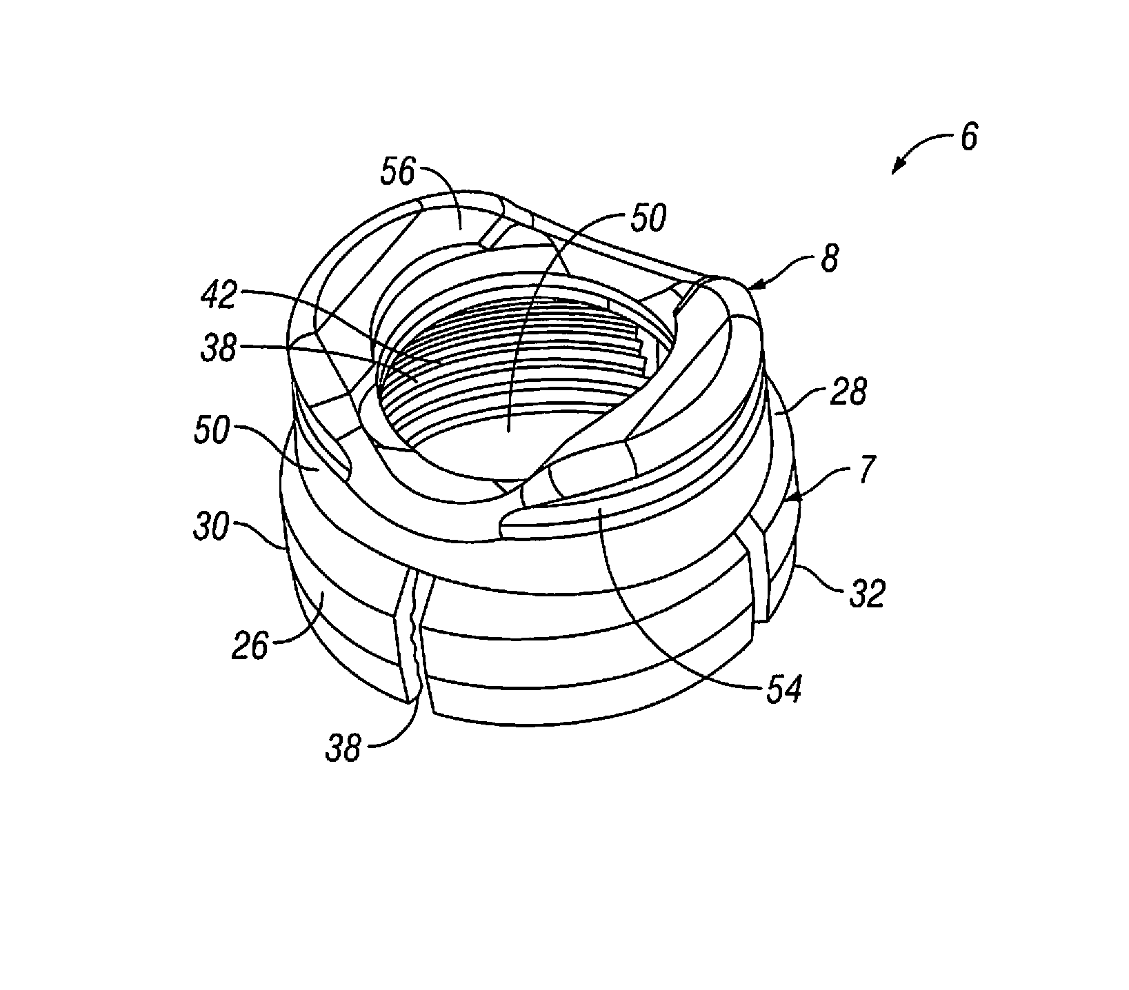
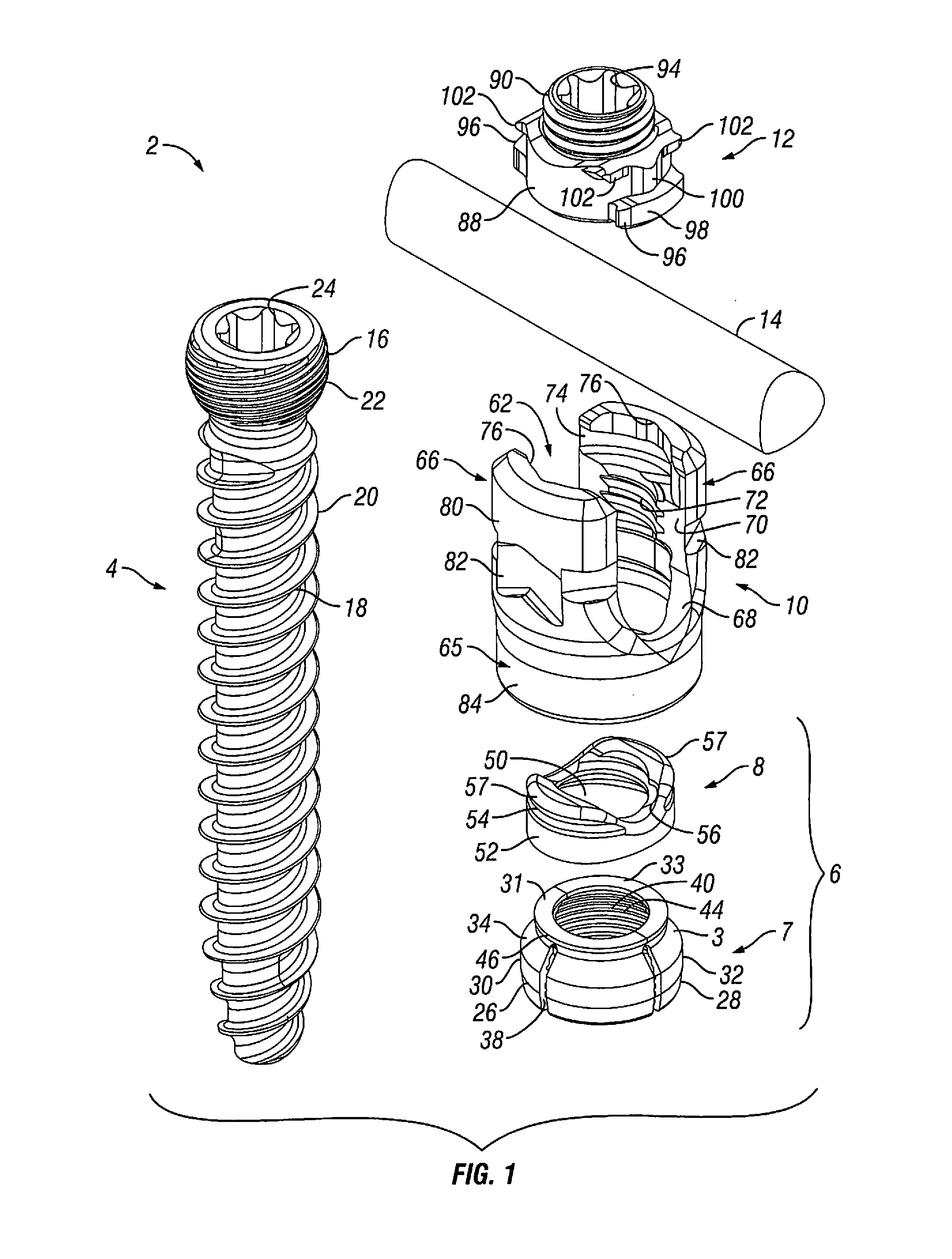
[0050]Embodiments of the present invention are generally directed to orthopedic fixation devices configured for bottom loading of the bone fastener. Instead of loading the bone fastener from the top of the tulip element, embodiments of the present invention load the bone fastener from the bottom of the tulip element. With the bone fastener loaded in the tulip element, a locking clamp assembly can then be used to secure the bone fastener therein. Thus, unlike prior orthopedic fixation devices, embodiments of the present invention permit the use of larger bone fasteners without having to also increase the size of the tulip element. This should, for example, reduce the needed inventory, decreasing the necessary graphic cases needed to perform a similar procedure, while decreasing in-house inventory costs.

[0051]Further, as explained by the examples and illustrations below, the bone fastener of the orthopedic fixation devices can be placed in the vertebra without the tulip element in acc...


PUM


Abstract

The present invention is generally directed to orthopedic fixation devices that comprise a coupling element and a bone fastener, whereby the bone fastener can be loaded into the coupling element through the bottom of a bore in the coupling element. The orthopedic fixation devices described herein can include modular locking clamp assemblies that can be fixed onto fasteners that are already implanted in bone. The modular locking clamp assemblies can include polyaxial locking clamp assemblies, as well as monoaxial locking clamp assemblies.

Description

CROSS REFERENCE TO RELATED APPLICATIONS[0001]This patent application is a continuation-in-part application of U.S. patent application Ser. No. 13 / 731,436, filed on Dec. 31, 2012, entitled “Orthopedic Fixation Devices and Methods of Installation Thereof,” which is a continuation-in-part application of U.S. patent application Ser. No. 13 / 183,965, filed on Jul. 15, 2011, entitled “Orthopedic Fixation Devices and Methods of Installation Thereof,” which are herein incorporated by reference in their entirety.FIELD OF THE INVENTION[0002]The present invention relates to orthopedic fixation devices, and, in one or more embodiments, to an orthopedic fixation device configured for loading of the bone fastener from the bottom of the tulip element.BACKGROUND OF THE INVENTION[0003]Many types of spinal irregularities can cause pain, limit range of motion, or injure the nervous system within the spinal column. These irregularities can result from, without limitation, trauma, tumor, disc degeneratio...

Claims


Application Information

Patent Timeline
IPC IPC(8): A61B17/70
CPCA61B17/7032A61B17/7001A61B17/7004A61B17/7011A61B17/7035A61B17/7047A61B17/7056A61B17/7082A61B17/7002A61B17/7037
Inventor MISHRA, DEVJEET
Owner GLOBUS MEDICAL INC
Why Eureka
Try Eureka