Offset orthopedic fixation device with locking mechanism

a technology of fixing device and locking mechanism, which is applied in the field of orthopaedic fixation device, can solve the problems of unfavorable loosening of screws once in place, and achieve the effect of compact configuration and space saving

Inactive Publication Date: 2010-09-21
AESCULAP AG
View PDF24 Cites 18 Cited by
  • Summary
  • Abstract
  • Description
  • Claims
  • Application Information

AI Technical Summary

Benefits of technology

[0007]For securing the transverse support on the fixation member, it is advantageous if the latter can be clamped in a defined angular position and / or axial position.
[0009]In order to move the clamp piece in the transverse support, it is possible in particular for a tensioning member to be mounted so that it engages against the clamp piece and is rotatable about a rotation axis. This affords a very compact configuration with which the transverse support can be released or secured relative to the fixation member. It is advantageous here if the angle of rotation of the tensioning member is limited in one direction or in both directions, for example by a limit stop. In this way, it is possible in particular to avoid a situation where the clamp piece is tensioned too strongly against the fixation member, which could result in the whole device being damaged. The defined rotatability between two end points also makes handling of the device easier for the operating surgeon.
[0012]A particularly advantageous construction is obtained if the transverse support has an oblong hole in which the fixation member, the clamp piece and the tensioning member are accommodated. This affords an especially space-saving and compact configuration which, if appropriate, allows the fixation member and the mounting body to be disposed very closely alongside one another.
[0015]It is advantageous here if the mounting body has seats for a stabilizing tool with which the mounting body, upon tensioning of the tensioning member, can be held securely so that no undesired torques are applied to the transverse support during tensioning of the tensioning member.
[0019]It is advantageous if the tensioning member is secured in the axial direction in the transverse support.
[0023]It is advantageous if the fixation member has a widening shaft, against which the clamp piece engages, and is mounted so as to be axially immovable and freely rotatable in the transverse support. The axial movement of the clamp piece thus secures the fixation member.

Problems solved by technology

However, in order to adjust the position of the transverse support, it is necessary also to turn the bone screw in the bone, and this can lead to undesired loosening of a screw once in place.

Method used


Image

  • Offset orthopedic fixation device with locking mechanism
  • Offset orthopedic fixation device with locking mechanism
  • Offset orthopedic fixation device with locking mechanism

Examples


Embodiment Construction

[0039]The ensuing detailed description provides exemplary embodiments only, and is not intended to limit the scope, applicability, or configuration of the invention. Rather, the ensuing detailed description of the exemplary embodiments will provide those skilled in the art with an enabling description for implementing an embodiment of the invention. It should be understood that various changes may be made in the function and arrangement of elements without departing from the spirit and scope of the invention as set forth in the appended claims.

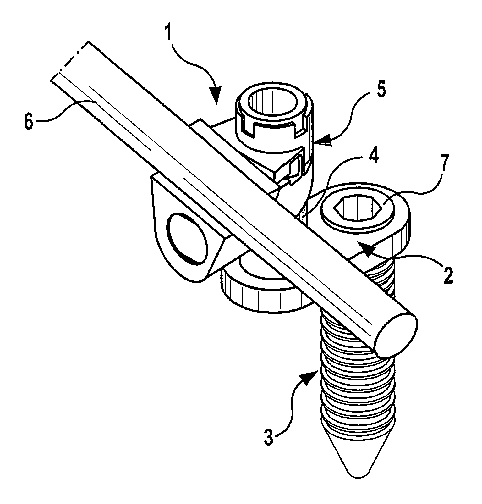
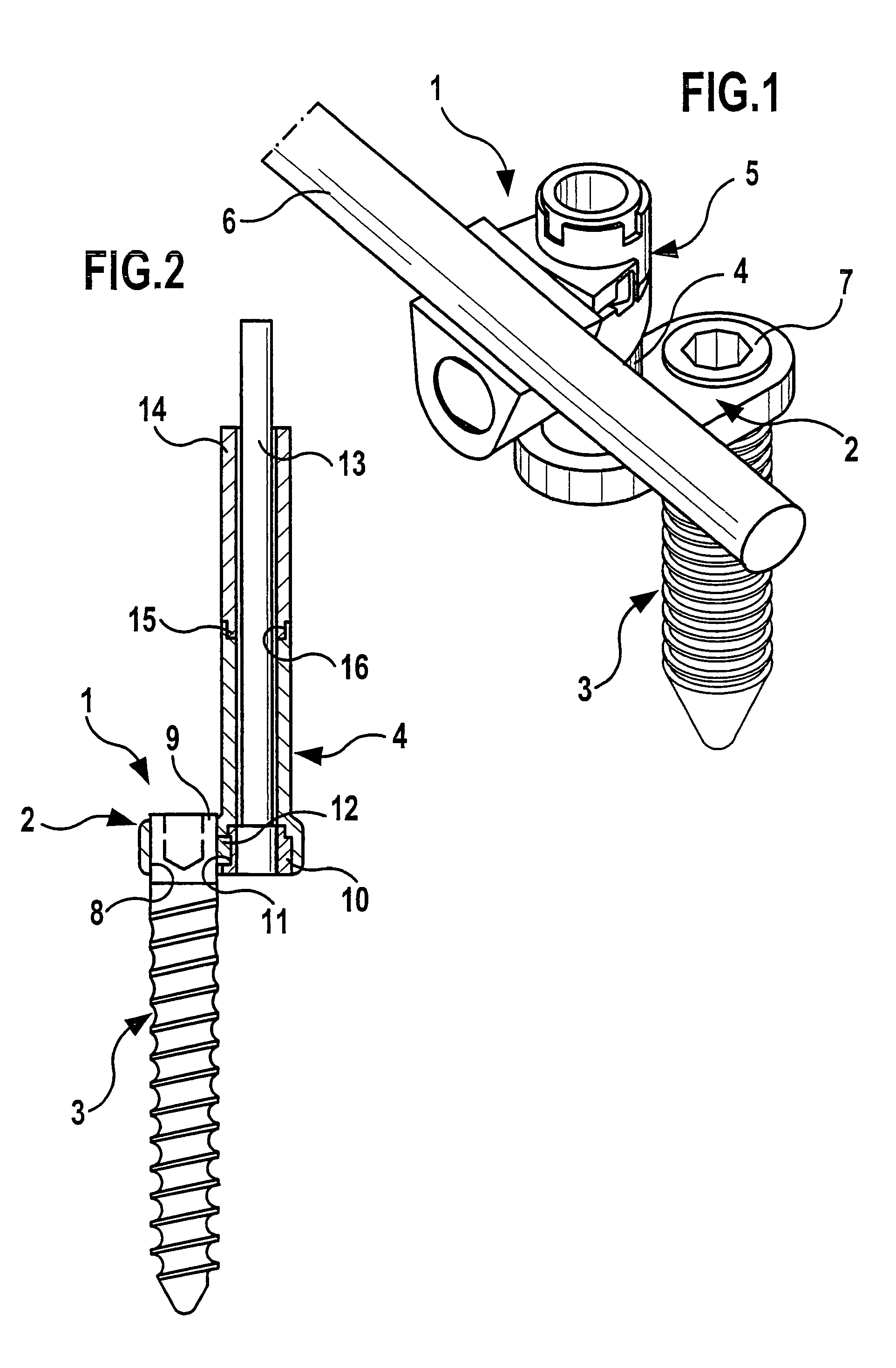
[0040]The fixation device 1 shown in FIG. 1 comprises a bone screw 3 with a plate-shaped transverse support 2 which can be secured at the upper end of the bone screw 3 and which in turn carries a sleeve-like, cylindrical mounting body 4. The bone screw 3 and the mounting body 4 are disposed parallel to one another and are laterally offset from one another by the transverse support 2.

[0041]A retaining device 5, shown in FIG. 1 but not explained...


PUM


Abstract

The invention relates to an orthopedic fixation device with an at least partly shaft-like fixation member, a shaft-like mounting body, and a transverse support securing the fixation member and the mounting body in a position in which they are laterally offset from one another. In order to adjust the transverse support without having to change the position of the fixation member, the fixation member can be rotated about its longitudinal axis in the transverse support and can be secured in a defined angular position.

Description

[0001]This application is a continuation of international application No. PCT / EP2002 / 009879 filed on Sep. 4, 2002, which is incorporated herein by reference in its entirety and for all purposes.BACKGROUND[0002]The invention relates to an orthopedic fixation device with an at least partly shaft-like fixation member, with a shaft-like mounting body, and with a transverse support securing the fixation member and the mounting body in a position in which they are laterally offset from one another.[0003]A fixation device of this kind is known, for example, from U.S. Pat. No. 5,545,228 in which a fixation member in the form of a bone screw carries a transverse support which is connected fixedly to it and at whose other end a mounting body in the form of an externally threaded pin is disposed. With this arrangement, it is possible for the mounting body to be disposed in a position laterally offset from the fixation member. In this way the operating surgeon, for example when using an orthope...

Claims


Application Information

Patent Timeline
Patent Type & Authority Patents(United States)
IPC IPC(8): A61B17/70
CPCA61B17/7035A61B17/7041
Inventor KRAMER, ULRICHSCHUMACHER, JOERGPOTULSKI, MICHAELBEISSE, RUDOLFKOZAK, JEFFREY ALAN
Owner AESCULAP AG
Why Eureka
Try Eureka