Robust modular electronic device without direct electrical connections for inter-module communication or control

a technology of electronic devices and direct electrical connections, applied in the direction of coupling device connections, electrical apparatus casings/cabinets/drawers, instruments, etc., can solve problems such as degrading device performance, and achieve the effects of enhancing device operation, reducing device performance, and facilitating protection

Active Publication Date: 2008-01-29
RAPP ROBERT
View PDF13 Cites 22 Cited by
  • Summary
  • Abstract
  • Description
  • Claims
  • Application Information

AI Technical Summary

Benefits of technology

[0013]Typically I / O (Input, Output) signals are more sensitive to damage from ESD than are power connections, and power connections are more easy to protect against ESD damage than are I / O signals. Filtering and transient suppression devices on power connections enhance device operation, where these components installed on I / O signals (especially high-speed I / O) degrade the device performance.
[0014]In this design I / O signals (those that are the most sensitive to ESD) remain protected inside the module, forever. Power connections implemented by inductive / transformer action provide an electrical contact-less design that is very resistant to ESD. Power connections implemented by direct connection offer high resistance to Electro-magnetic Pulse (EMP) offer modest native resistance to ESD, an attribute that can be enhanced easily and at low cost.

Problems solved by technology

Filtering and transient suppression devices on power connections enhance device operation, where these components installed on I / O signals (especially high-speed I / O) degrade the device performance.

Method used


Image

  • Robust modular electronic device without direct electrical connections for inter-module communication or control
  • Robust modular electronic device without direct electrical connections for inter-module communication or control
  • Robust modular electronic device without direct electrical connections for inter-module communication or control

Examples


example 1

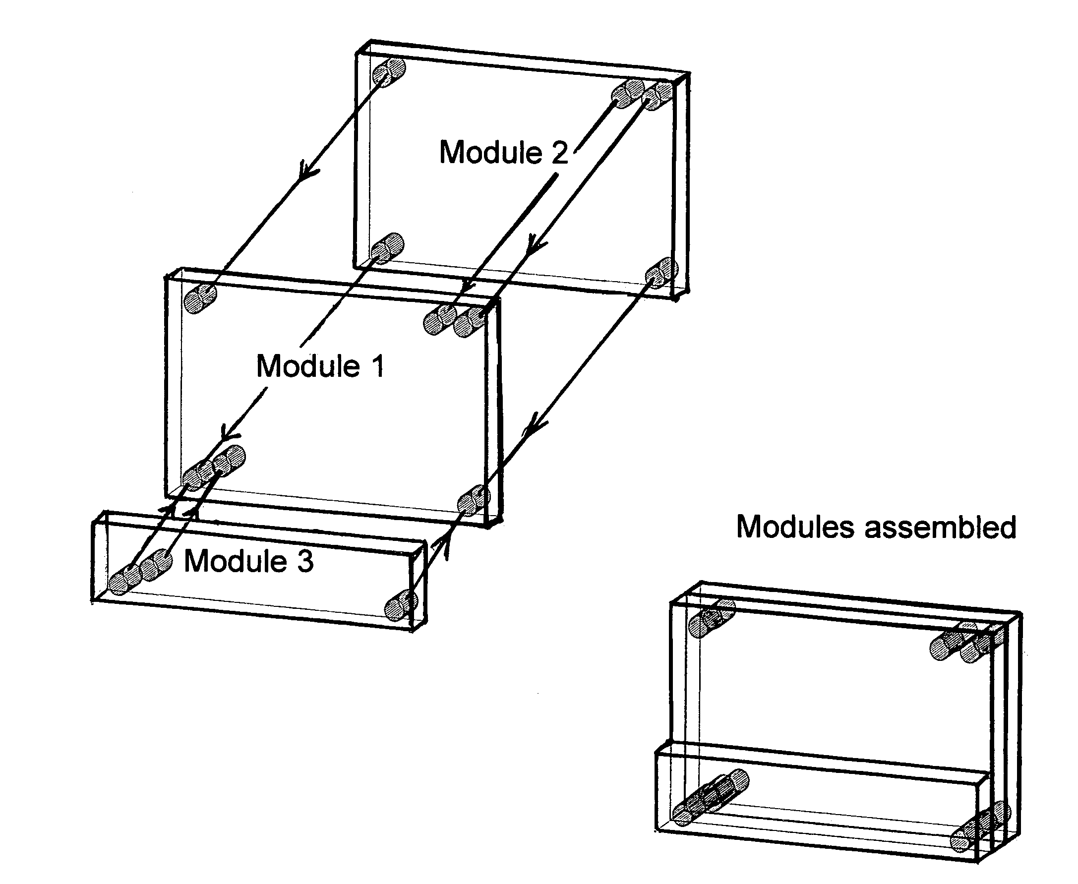
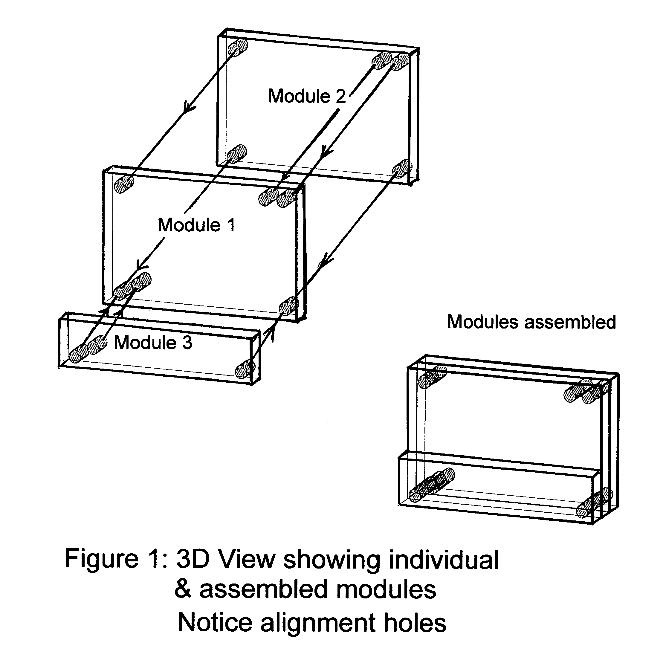
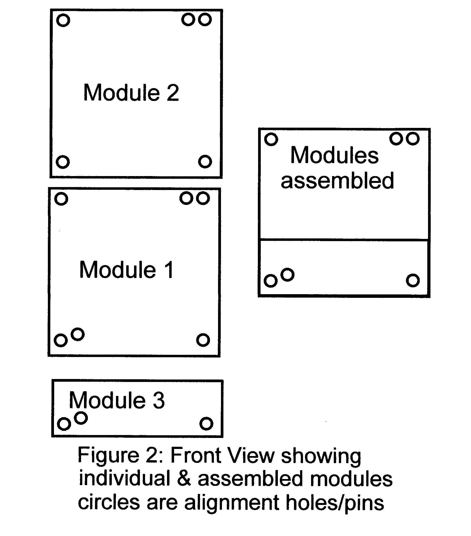
[0086]Assumptions for One Hypothetical application, an implementation with no inter-module electrical connections:[0087]There is a main function module, which contains an electronic camera, a small LCD screen, magnetic control switches, a small memory, a flash unit, and strategically located inductive receiver / transmitter pairs.[0088]A second module, a power module has alignment pins that fit into alignment holes on front side of the camera. One alignment pin acts as the core of a power transformer. Power is conducted inductively to and potentially through the camera module to other modules. A magnet inside of the camera module applies a retention force to the second alignment ping that holds the modules together.[0089]A third module, a memory extension module connects to the backside of the camera through small alignment pins. This module like module 2 is magnetically retained, and contains an inductive power transfer element. Here, however the alignment pins also align inductive t...

example 2

[0091]Assumptions for one Hypothetical application, an implementation with direct power interconnects:[0092]There is a main function module, which contains an electronic camera, a small LCD screen, magnetic control switches, a small memory, a flash unit, and strategically located inductive receiver / transmitter pairs.[0093]A second module, a battery module has small alignment pins that fit into alignment holes on the left side of the camera. These alignment pins align power and ground connections which connect when the modules are pressed together. Magnets inside of the camera module apply retention force that holds the modules together.[0094]A third module, a memory extension module connects to the right side of the camera through small alignment pins. This module like module 2 is magnetically retained, and contains power interconnects. Here, however the alignment pins also align inductive transmitters and receivers used to transfer data between modules 1 and 2.[0095]A fourth module...

example 3

[0096]In this case the implementation is a sealed yet extendable computer built with features of this new method, yet in this case one or more modules are liquid filled. The fluid cools electronic components and / or provides resistance to crushing when in a high-pressure environment. In this example the fabrication process includes:[0097]The case consists of two pieces, a top and a bottom.[0098]The electronic module is mounted inside the case's bottom part and connected to non-contact communication transceivers and power mechanisms.[0099]The top of the case is sealed onto the bottom using epoxy, gasket material, RTV, silicone, or other airtight sealing mechanism that (potentially) conduct heat through the seal.[0100]The module is filled with a liquid (such as Flourinert 3M trademarked coolant, or a non-electrically conductive oil) through a small access hole.[0101]The access hole is itself sealed thus completing the module's assembly.


PUM


Abstract

A modular electronic device where (predominantly) sealed modules are aligned and attached / connected in pre-determined sequences, forming a robust block-like structure with extendable function: Control and / or inter-module communication are implemented without direct electrical interconnect, by non-contact means such as (magnetic, inductive, light, infrared, radio frequency, sound, ultrasound, or other non-contact means). This device's inter-module power transfer may be with or without direct electrical contact, or devices may be internally powered. Power transfer through inductive / transformer action where one or more alignment pins are used as transformer core is one potential implementation. Modules may be fluid filled to facilitate cooling and / or crush resistance to high-pressure environments.

Description

CROSS REFERENCE TO RELATED APPLICATIONS[0001]This application is entitled to the benefit of Provisional Patent application No. 60 / 458,619 filed Mar. 27, 2003.FEDERAL RESEARCH STATEMENT[0002]Not Applicable, this invention was developed without government assistance, it was developed on my time and with my (Robert J. Rapp) resources.BACKGROUND OF INVENTION[0003]Modular electronic devices typically have numerous (a plurality of) electrical interconnections. These interconnections are subject to shorting, crimping, crushing, ESD, and environmental contamination when those connections / connectors are exposed.[0004]Robust electronic devices are typically built to withstand certain environments, some are built to withstand shock, others are built to withstand rain or dust, while still others are built to withstand immersion in water to various depths. If extendable, these devices typically have to be opened and new components installed inside of the device's enclosure, thus exposing interna...

Claims


Application Information

Patent Timeline
Patent Type & Authority Patents(United States)
IPC IPC(8): H01R13/502G06F1/16G06F1/18H04N5/225H05K5/00
CPCH04N5/2251H05K5/0021G06F1/16G06F1/182Y10S439/95
Inventor RAPP, ROBERT
Owner RAPP ROBERT
Why Eureka
Try Eureka