Molded-case circuit breaker

Active Publication Date: 2014-10-16
LSIS CO LTD
View PDF7 Cites 7 Cited by
  • Summary
  • Abstract
  • Description
  • Claims
  • Application Information

AI Technical Summary

Benefits of technology

[0012]According to an embodiment of the present invention, an electrode shaft is installed outside a front space and a rear space, thereby substantially reducing a height of a product or preventing an increase in size of the product. Accordingly, not only the size of the product is reduced but also a size of a space, to which an arc is substantially transferred, is reduced, thereby preventing the transfer of the arc.

Problems solved by technology

However, the general molded case circu

Method used


Image

  • Molded-case circuit breaker
  • Molded-case circuit breaker
  • Molded-case circuit breaker

Examples


Embodiment Construction

[0020]Hereinafter, an embodiment of the present invention will be described in detail with reference to the attached drawings.

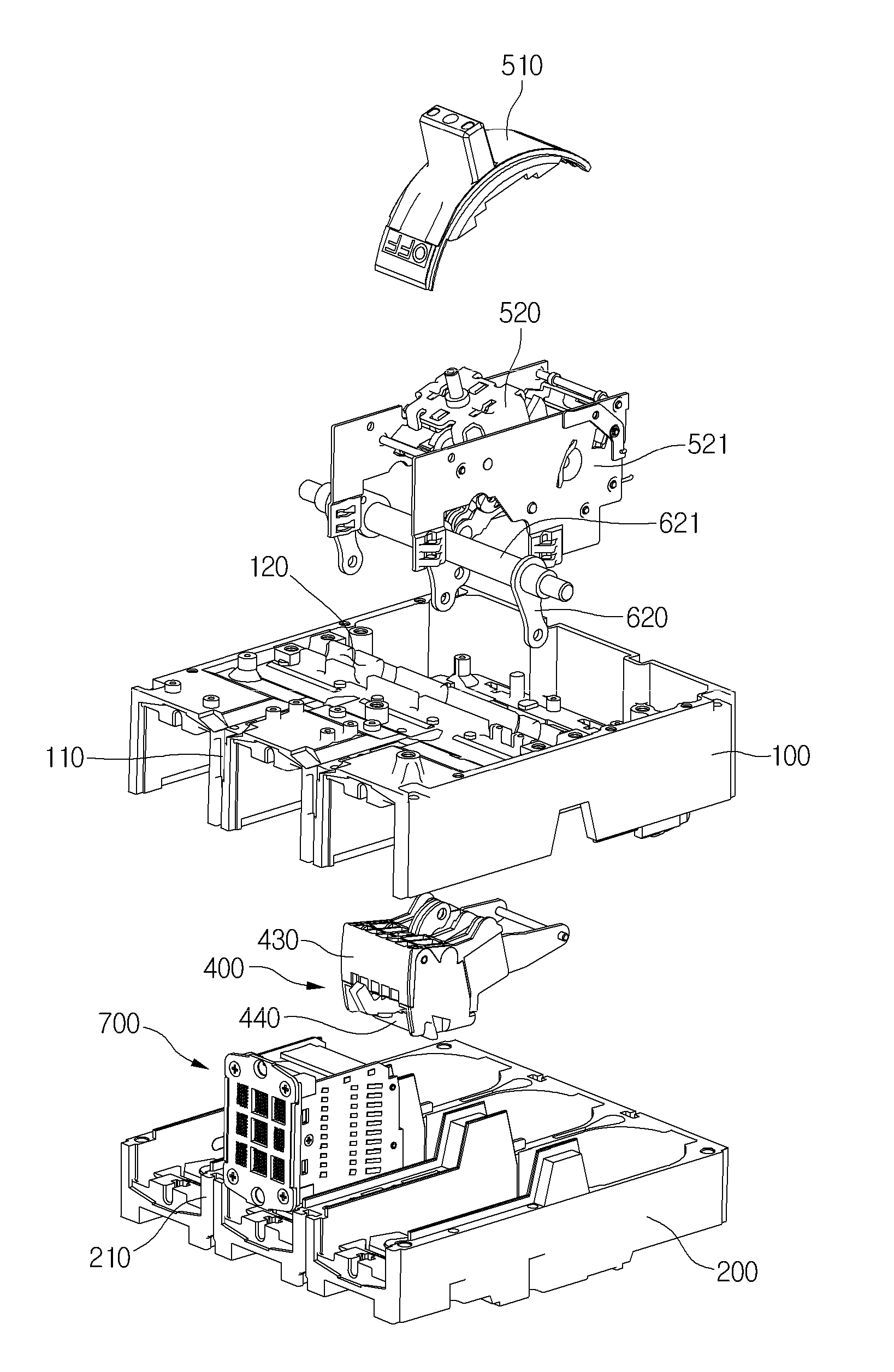
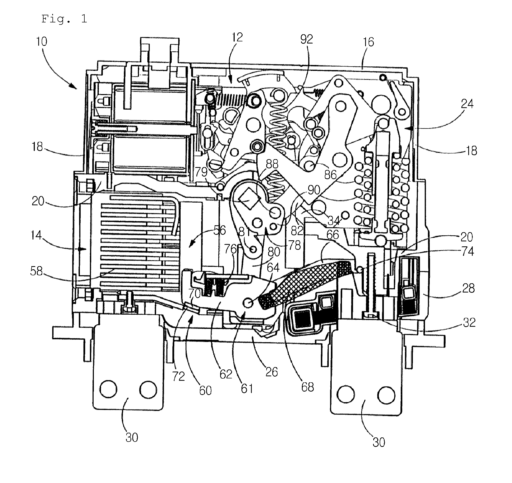
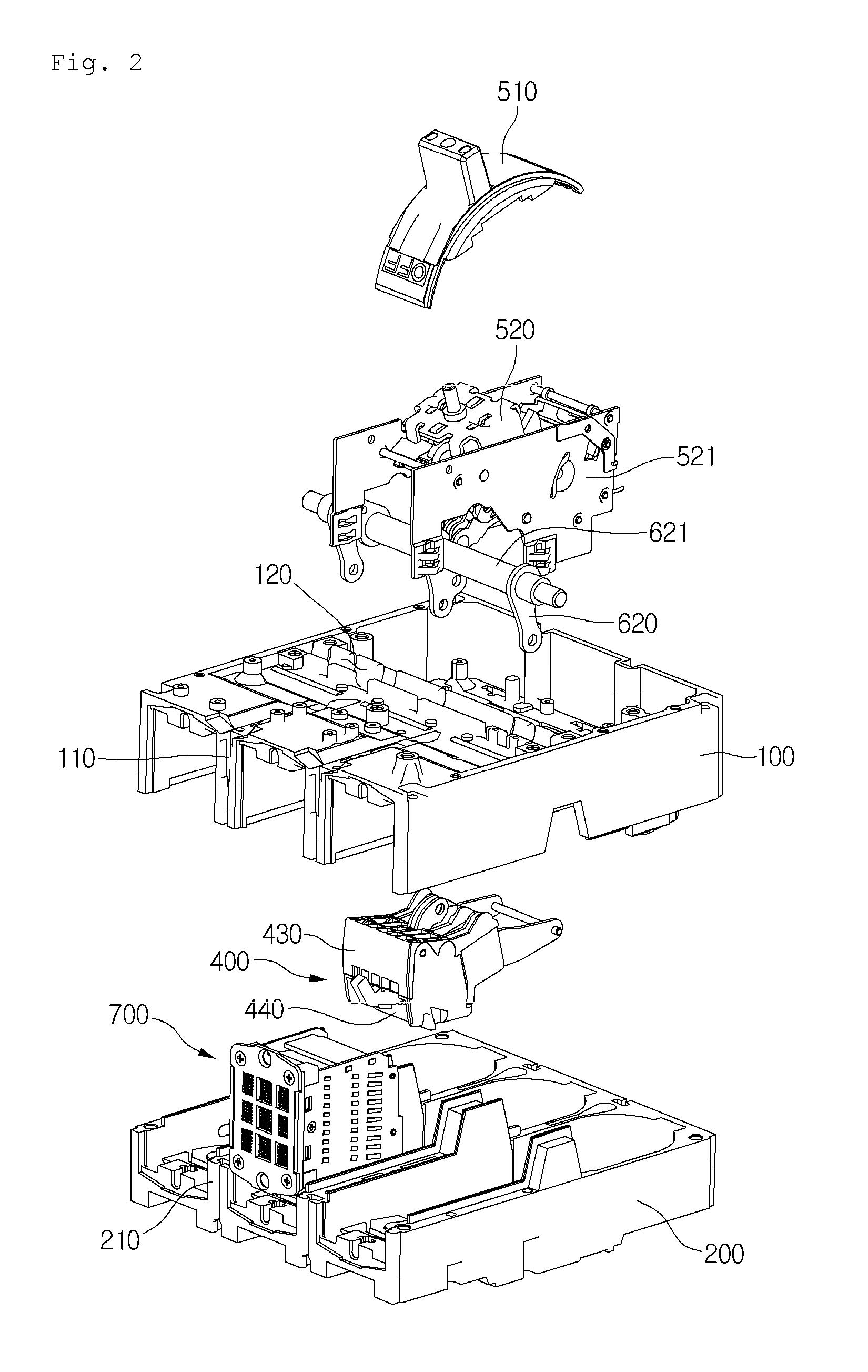
[0021]FIG. 2 is an exploded perspective view of a molded case circuit breaker 1 according to an embodiment of the present invention, FIG. 3 is a cross-sectional view illustrating a closed state according to an embodiment of the present invention, and FIG. 4 is an exploded perspective view a main part according to an embodiment of the present invention.

[0022]Referring to FIGS. 2 to 4, an external shape of the molded case circuit breaker 1 is formed of an upper external box 100 and a lower external box 200. Also, the upper external box 100 and the lower external box 200 are coupled with each other, thereby defining an installation space installed with all sorts of components forming the circuit breaker 1. For example, the upper external box 100 may be formed as a polyhedral shape with open bottom and front. Also, the lower external box 200 may be formed as a po...


PUM


Abstract

Provided is a molded case circuit breaker including a front space, a rear space divided from the front space, a fixed contact unit provided on one side of the front space and in electric contact with one of a power supply and a load, a movable contact unit installed in the front space to be movable and in contact with the fixed contact unit, a switching device installed in the rear space and operating to allow the movable contact unit to be in selective contact with the fixed contact unit, an operation device installed in the front space and the rear space and transferring the movable contact unit according to operation of the switching device, an arc extinguishment chamber installed on the one side of the front space and extinguishing an arc induced while the fixed contact unit is being separated from the movable contact unit, and a barrier preventing backward movement of the arc from at least one position of a moving way of the movable contact unit, the position separate from the fixed contact unit.

Description

TECHNICAL FIELD[0001]The present invention relates to a molded case circuit breaker.BACKGROUND ART[0002]Molded case circuit breakers, when an abnormal current such as an over current and a short-circuit current is applied to a circuit, protect the circuit by breaking the circuit. In molded case circuit breakers described above, it is necessary to interrupt an arc induced at an opening time that a fixed contact point and a movable contact point are separated from each other when breaking the circuit.[0003]FIG. 1 illustrates a general molded case circuit breaker disclosed in Korean Patent Publication No. 2001-0043240.[0004]Referring to FIG. 1, in general, a front compartment 12 and a rear compartment mutually divided from each other are located in a molded case circuit breaker 10. Also, a fixed contact point 60 and a movable contact point 61 are located in the front compartment 12 and a driving device for transferring the movable contact point 61, and particularly, an electrode shaft ...

Claims


Application Information

Patent Timeline
IPC IPC(8): H01H33/08
CPCH01H33/08H01H71/0235H01H71/10H01H73/18H01H2009/305
Inventor BAEK, KI HO
Owner LSIS CO LTD
Why Eureka
Try Eureka