Imaging lens and imaging apparatus

a technology of imaging lens and imaging apparatus, which is applied in the field of imaging lens, can solve the problems of inevitably long optical total length of such type of imaging lens, and achieve the effects of reducing the size of imaging lens, excellently correcting chromatic aberration, and suppressing the exit angle of peripheral rays

Active Publication Date: 2014-10-16
FUJIFILM CORP
View PDF1 Cites 10 Cited by
  • Summary
  • Abstract
  • Description
  • Claims
  • Application Information

AI Technical Summary

Benefits of technology

[0049]The imaging lens of the present invention can correct various aberrations, such as a spherical aberration, curvature of field and chromatic aberrations, generated in the first lens group, in a well-balanced manner when the first lens group substantially consists of at least one negative lens and a positive lens. Further, since a cemented lens is provided in the second lens group, it is possible to excellently correct chromatic aberrations. Further, since a single lens having positive power is arranged on the image-plane side of the cemented lens, it is possible to suppress the exit angle of peripheral rays without making the back focus too lon...

Problems solved by technology

The optical total length of such type of imaging lens inevitably b...

Method used


Image

  • Imaging lens and imaging apparatus
  • Imaging lens and imaging apparatus
  • Imaging lens and imaging apparatus

Examples


example 1

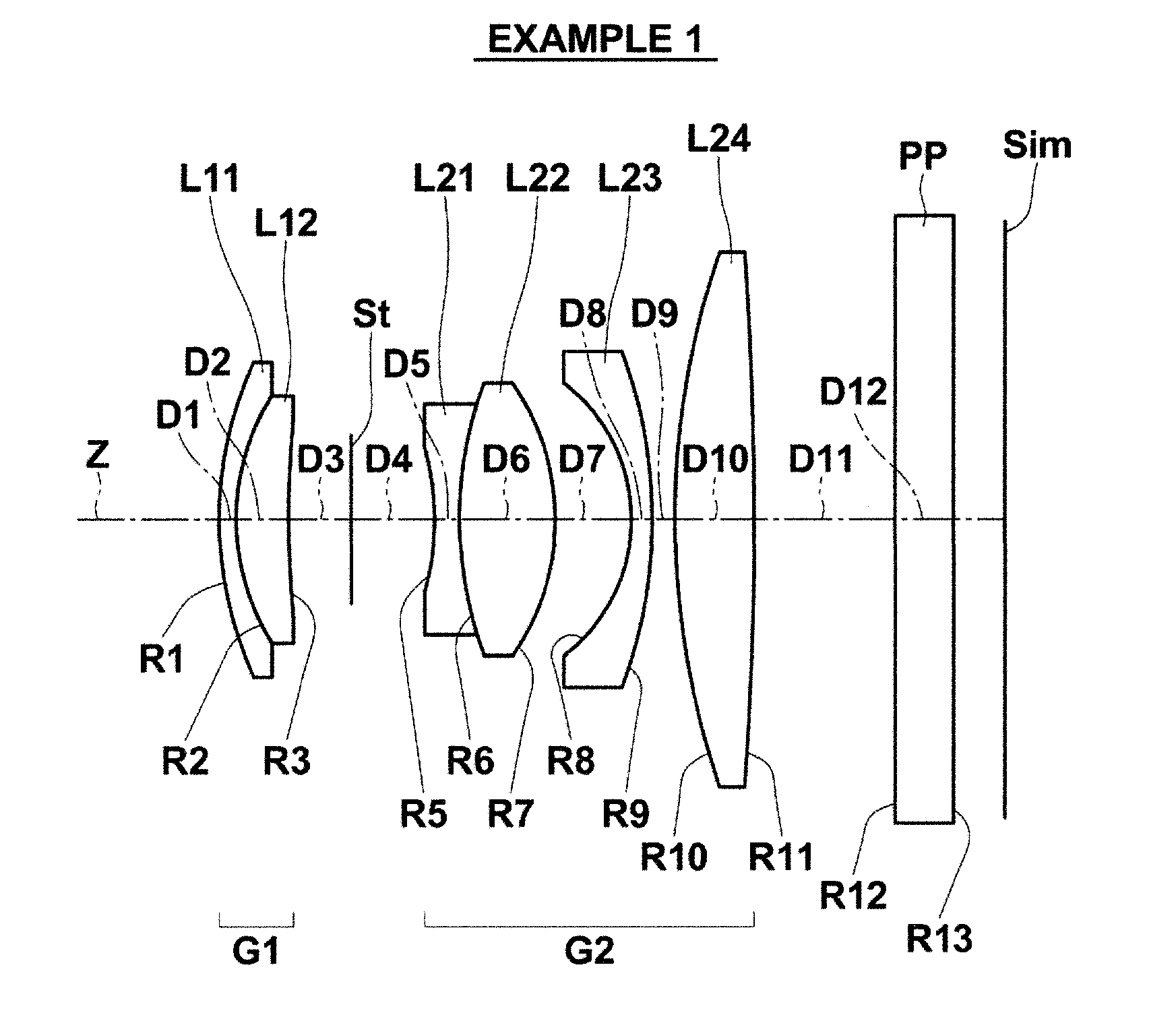
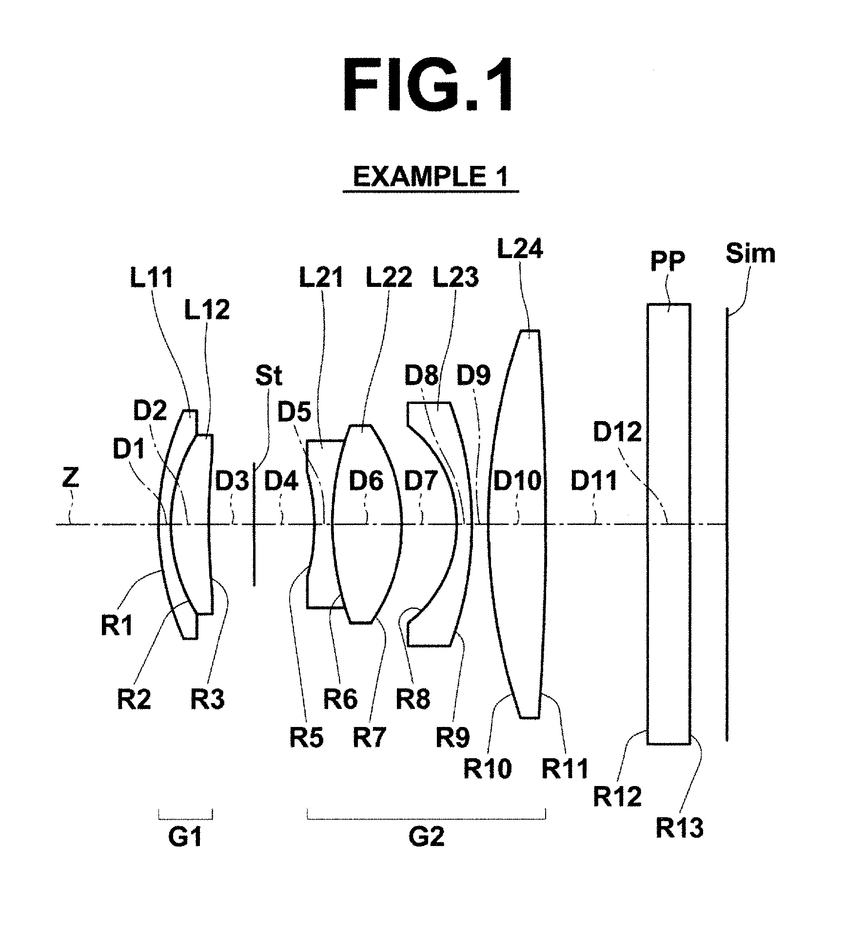
[0125]FIG. 1 is a diagram illustrating the arrangement of lens groups in an imaging lens of Example 1. Since the lens groups and each lens in the structure of FIG. 1 were described in detail already, explanations will not be repeated in the following descriptions, unless especially necessary.

[0126]Table 1 shows basic lens data on the imaging lens of Example 1. Here, data including optical member PP are shown. In Table 1, column Si shows the surface number of the i-th surface (i=1, 2, 3, . . . ). The object-side surface of a composition element located closest to the object side is the first surface, and surface numbers are assigned to composition elements in such a manner to sequentially increase toward the image side. Column Ri shows the curvature radius of the i-th surface, and column Di shows a distance on optical axis Z between the i-th surface and the (i+1)th surface. Column Ndj shows the refractive index of the j-th composition element (j=1, 2, 3, . . . ) for d-line (wavelengt...

example 2

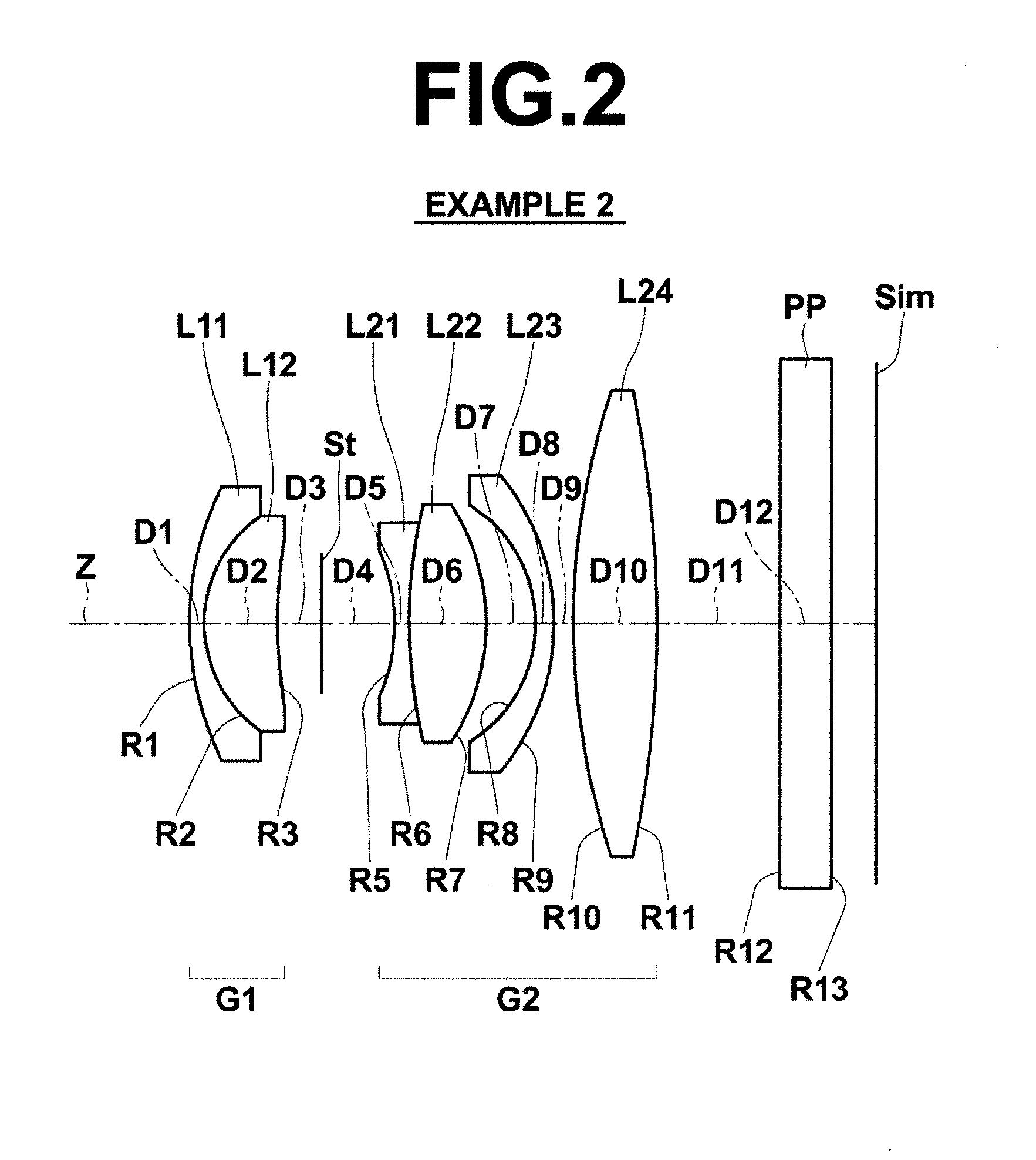
[0131]FIG. 2 is a diagram illustrating the arrangement of lens groups in the imaging lens of Example 2. Table 2 shows basic lens data on the imaging lens of Example 2. FIG. 9, Sections A through D are aberration diagrams of the imaging lens of Example 2.

TABLE 2EXAMPLE 2• BASIC LENS DATARiNdjSi(CURVA-Di(REFRAC-ν dj(SURFACETURE(SURFACETIVE(ABBENUMBER)RADIUS)DISTANCE)INDEX)NUMBER)116.80640.811.68893131.0727.17454.001.88299740.76328.80451.694∞(STOP)4.005−9.74550.811.84666023.78628.71514.201.90365831.327−12.02272.708−7.64151.001.62299258.169−12.64681.061040.13684.601.71299553.8711−61.25061.6912∞2.801.55000055.0013∞f = 28.803FNo. = 2.88

example 3

[0132]FIG. 3 is a diagram illustrating the arrangement of lens groups in the imaging lens of Example 3. Table 3 shows basic lens data on the imaging lens of Example 3. Further, in the lens data of Table 3, the mark of “*” is attached to the surface number of an aspherical surface, and the numerical value of a paraxial curvature radius is shown, as the curvature radius of the aspherical surface.

[0133]Table 4 shows aspherical surface data on the imaging lens of Example 3. Here, the aspherical surface data show the surface number of an aspherical surface and aspherical surface coefficients about the aspherical surface. Here, the numerical value of “E−n” (n: integer) of the aspherical surface coefficient means “×10−n”. The aspherical surface coefficients are values of coefficients KA, Am (m=3, 4, 5, . . . 10) in the following aspherical equation:

zd=C·h2 / {1+(1−KA·C2·h2)1 / 2}+ΣAm·hm, where

[0134]Zd: depth of an aspherical surface (the length of a perpendicular from a point on the aspher...


PUM


Abstract

An imaging-lens substantially consists of a first-lens-group, a stop and a second-lens-group in this order from object-side. The first-lens-group substantially consists of three or less lenses including a negative-lens arranged closest to object-side and a positive-lens arranged on image-side of the negative-lens. The first-lens-group includes a negative-lens having a meniscus-shape with its convex-surface facing object-side and a positive-lens cemented on the negative-lens in this order from object-side. The second-lens-group substantially consists of five or less lenses including a cemented-lens of two lenses of a positive-lens and a negative-lens and a single-lens having positive-refractive-power, and which is arranged on image-side of the cemented-lens. Conditional-formulas about a refractive-index and an Abbe-number of the negative-lens arranged closest to the object-side in the first-lens-group for d-line, Abbe-numbers of the positive-lens and the negative-lens constituting the cemented-lens in the second-lens-group for d-line, and a refractive-index of the single-lens constituting the second-lens-group for d-line are satisfied.

Description

CROSS-REFERENCE TO RELATED APPLICATIONS[0001]This application is a Continuation of PCT International Application No. PCT / JP2012 / 008260 filed on Dec. 25, 2012, which claims priority under 35 U.S.C. §119 (a) to Japanese Patent Application No. 2011-284632 filed on Dec. 27, 2011. Each of the above applications is hereby expressly incorporated by reference, in its entirety, into the present application.BACKGROUND OF THE INVENTION[0002]1. Field of the Invention[0003]The present invention relates to an imaging lens, and particularly to a small-size lens appropriate for an imaging apparatus, such as an electronic camera. Further, the present invention relates to an imaging apparatus including such an imaging lens.[0004]2. Description of the Related Art[0005]In recent years, many digital cameras with large-size imaging devices for example by APS format, Four Thirds format or the like mounted therein were provided for the market. Recently, not only digital single-lens reflex cameras but also ...

Claims


Application Information

Patent Timeline
IPC IPC(8): G02B13/00
CPCG02B13/0045G02B13/002G02B13/0015
Inventor KAWAMURA, DAIKI
Owner FUJIFILM CORP
Why Eureka
Try Eureka