Optical lens, camera module and electronic equipment

An optical lens and lens technology, applied in optics, optical components, instruments, etc., can solve problems such as the difficulty in meeting the miniaturization of electronic equipment, wide-viewing requirements, and unfavorable imaging quality, so as to delay the edge light angle, improve imaging quality, Shorten the effect of correcting aberrations

Pending Publication Date: 2021-12-03
JIANGXI JINGCHAO OPTICAL CO LTD
View PDF0 Cites 1 Cited by
  • Summary
  • Abstract
  • Description
  • Claims
  • Application Information

AI Technical Summary

Problems solved by technology

In related technologies, there are big problems in the design and manufacture of optical lenses for electronic equipment such as mobile phones in terms of miniaturization and wide-viewing. It is difficult to meet the requirements of miniaturization and wide-screening of electronic equipment, which is not conducive to improving image quality

Method used


Image

  • Optical lens, camera module and electronic equipment
  • Optical lens, camera module and electronic equipment
  • Optical lens, camera module and electronic equipment

Examples


Embodiment 1

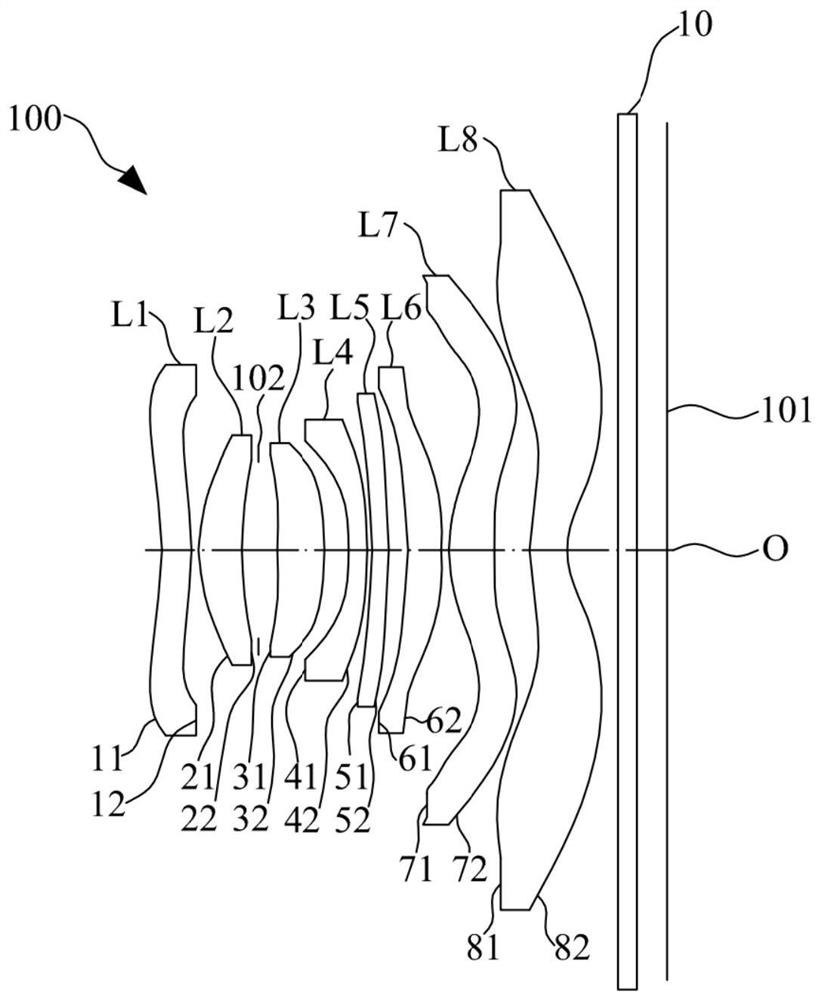
[0076] The structural schematic diagram of the optical lens 100 disclosed in Embodiment 1 of the present invention is as follows figure 1As shown, the optical lens 100 includes a first lens L1, a second lens L2, a diaphragm 102, a third lens L3, a fourth lens L4, a fifth lens L5, a first lens L1, and a second lens L1 arranged sequentially from the object side to the image side along the optical axis O. Six lenses L6, a seventh lens L7, an eighth lens L8 and a filter 10.

[0077] Further, the first lens L1 has a negative refractive power, the second lens L2 has a positive refractive power, the third lens L3 has a positive refractive power, the fourth lens L4 has a negative refractive power, and the fifth lens L5 has a positive refractive power, Sixth lens L6 has negative refractive power, seventh lens L7 has positive refractive power, and eighth lens L8 has negative refractive power.

[0078] Further, the object side 11 and image side 12 of the first lens L1 are respectively c...

Embodiment 2

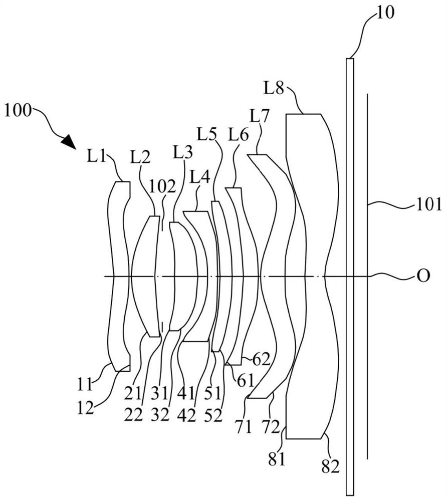
[0092] The structural schematic diagram of the optical lens 100 disclosed in Embodiment 2 of the present invention is as follows image 3 As shown, the optical lens 100 includes a first lens L1, a second lens L2, a diaphragm 102, a third lens L3, a fourth lens L4, a fifth lens L5, a first lens L1, and a second lens L1 arranged sequentially from the object side to the image side along the optical axis O. Six lenses L6, a seventh lens L7, an eighth lens L8 and a filter 10.

[0093] Further, the first lens L1 has a negative refractive power, the second lens L2 has a positive refractive power, the third lens L3 has a positive refractive power, the fourth lens L4 has a negative refractive power, and the fifth lens L5 has a positive refractive power, Sixth lens L6 has negative refractive power, seventh lens L7 has positive refractive power, and eighth lens L8 has negative refractive power.

[0094] Further, the object side 11 and image side 12 of the first lens L1 are respectively ...

Embodiment 3

[0104] The structural schematic diagram of the optical lens 100 disclosed in Embodiment 3 of the present invention is as follows Figure 5 As shown, the optical lens 100 includes a first lens L1, a second lens L2, a diaphragm 102, a third lens L3, a fourth lens L4, a fifth lens L5, a first lens L1, and a second lens L1 arranged sequentially from the object side to the image side along the optical axis O. Six lenses L6, a seventh lens L7, an eighth lens L8 and a filter 10.

[0105]Further, the first lens L1 has a negative refractive power, the second lens L2 has a positive refractive power, the third lens L3 has a positive refractive power, the fourth lens L4 has a negative refractive power, and the fifth lens L5 has a negative refractive power , the sixth lens L6 has negative refractive power, the seventh lens L7 has positive refractive power, and the eighth lens L8 has negative refractive power.

[0106] Further, the object side 11 and image side 12 of the first lens L1 are ...


PUM


Abstract

The invention discloses an optical lens, a camera module and electronic equipment, and the optical lens comprises a first lens which is sequentially provided with negative focal power from an object side to an image side along an optical axis, wherein the object side surface and the image side surface of the first lens are a concave surface and a convex surface; a second lens with positive focal power, wherein the object side surface and the image side surface of the second lens are a convex surface and a concave surface; a third lens with positive focal power, wherein the image side surface of the third lens is a convex surface; a fourth lens with focal power, wherein the object side surface and the image side surface of the fourth lens are a concave surface and a convex surface; a fifth lens with focal power, wherein the object side surface and the image side surface of the fifth lens are a concave surface and a convex surface; a sixth lens with negative focal power, wherein the object side surface and the image side surface of the sixth lens are a concave surface and a convex surface; a seventh lens with positive focal power, wherein the object side surface of the seventh lens is a convex surface; and an eighth lens with negative focal power, wherein the object side surface and the image side surface of the eighth lens are a convex surface and a concave surface. The optical lens also satisfies the following relational expression: 0.15 mm < TTL / (ImgH * 2) / f < 0.2 mm. According to the optical lens, the camera module and the electronic equipment provided by the embodiment of the invention, the shooting requirements of miniaturization and wide view can be met, and the imaging quality of the electronic equipment is improved.

Description

technical field [0001] The invention relates to the technical field of optical imaging, in particular to an optical lens, a camera module and electronic equipment. Background technique [0002] With people's pursuit of miniaturization and wide viewing of electronic products, the structural characteristics of light, thin and miniaturized optical lenses have gradually become the development trend of optical lenses. In related technologies, there are big problems in the design and manufacture of optical lenses for electronic equipment such as mobile phones in terms of miniaturization and wide viewing, and it is difficult to meet the requirements of miniaturization and wide viewing of electronic equipment, which is not conducive to improving image quality. Contents of the invention [0003] The embodiment of the invention discloses an optical lens, a camera module and electronic equipment, which can meet the requirements of miniaturization and wide viewing of the electronic eq...

Claims


Application Information

Patent Timeline
IPC IPC(8): G02B13/00G02B13/18G02B13/06
CPCG02B13/0015G02B13/0045G02B13/06G03B30/00
Inventor 刘彬彬邹海荣李明
Owner JIANGXI JINGCHAO OPTICAL CO LTD
Why Eureka
Try Eureka