Shear band with interlaced reinforcements

a technology of reinforcements and shear bands, applied in the direction of wheel attachments, tyre parts, transportation and packaging, etc., can solve the problems of inability to meet the requirements affecting the effect of reducing the mass of materials, and causing the increase of the mass of materials required

Active Publication Date: 2014-11-06
MICHELIN & CO CIE GEN DES ESTAB MICHELIN
View PDF16 Cites 36 Cited by
  • Summary
  • Abstract
  • Description
  • Claims
  • Application Information

AI Technical Summary

Benefits of technology

[0009]In one exemplary embodiment, the present invention provides an annular shear band defining axial, radial, and circumferential directions. The annular shear band includes an annular shear layer constructed from at least one elastomeric material. A plurality of discrete, annular reinfor

Problems solved by technology

For non-pneumatic tires employing a shear band having a homogenous shear layer, challenges are encountered in making such reductions.
For example, the use of materials for the shear

Method used


Image

  • Shear band with interlaced reinforcements
  • Shear band with interlaced reinforcements
  • Shear band with interlaced reinforcements

Examples


Embodiment Construction

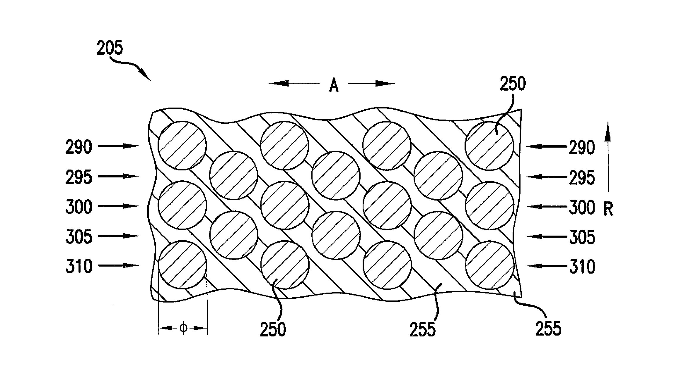
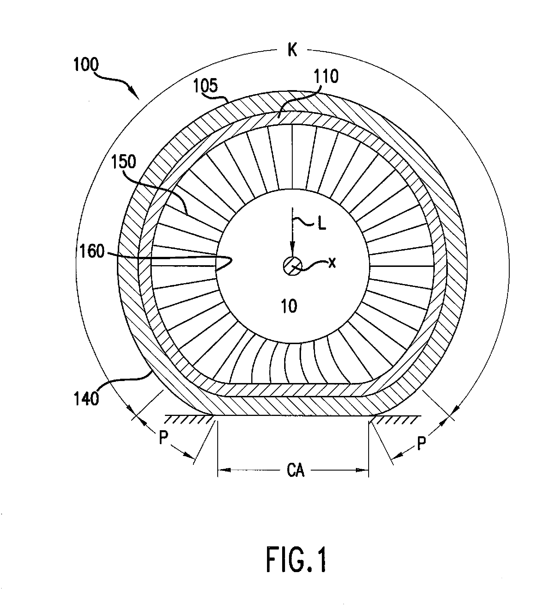
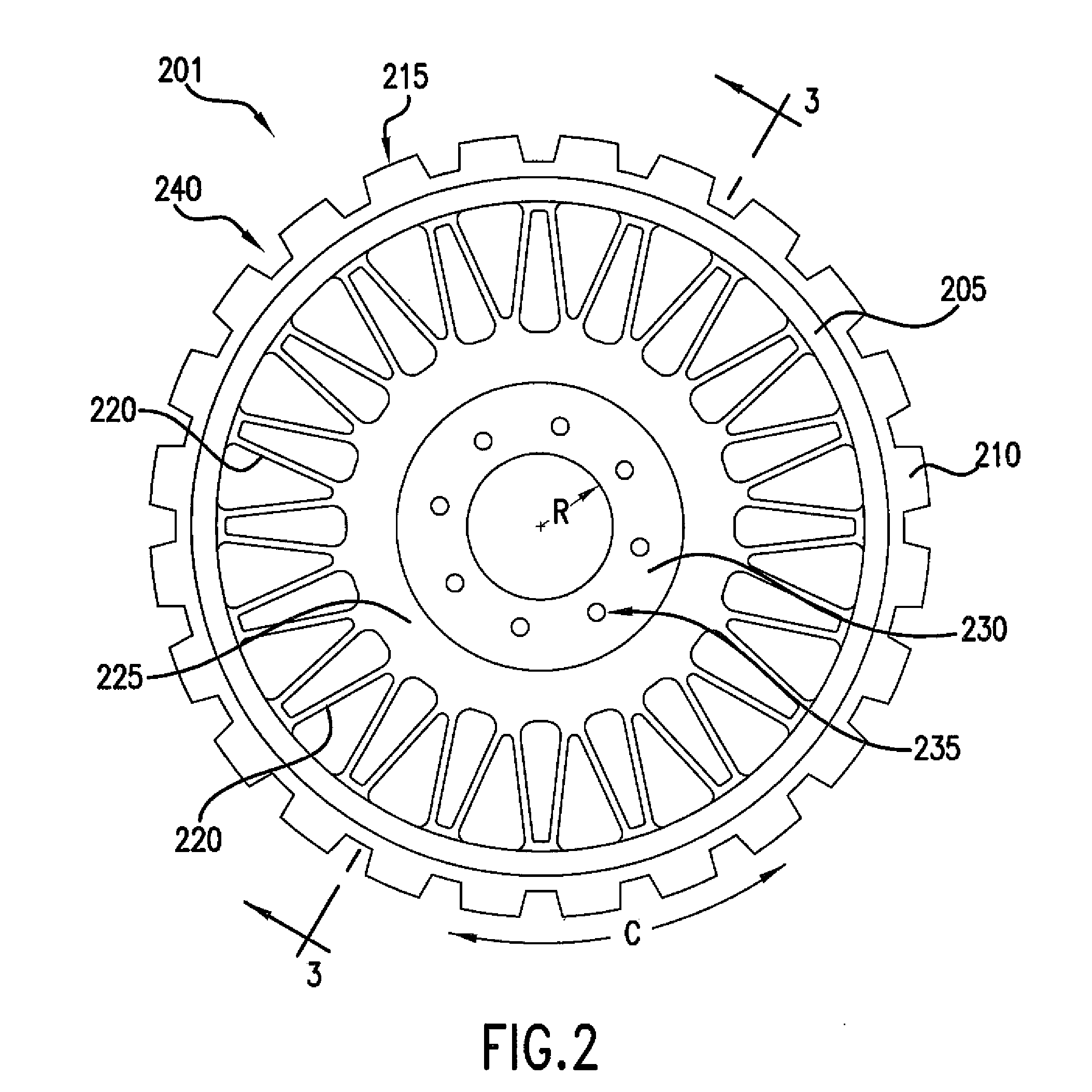
[0021]The present invention provides a shear band that may be used e.g., in a non-pneumatic tire. The shear band uses interlaced reinforcing elements positioned within a shear layer of elastomeric material. A variety of configurations may be used to create the interlaced positioning of the reinforcing elements. For purposes of describing the invention, reference now will be made in detail to embodiments and / or methods of the invention, one or more examples of which are illustrated in or with the drawings. Each example is provided by way of explanation of the invention, not limitation of the invention. In fact, it will be apparent to those skilled in the art that various modifications and variations can be made in the present invention without departing from the scope or spirit of the invention. For instance, features or steps illustrated or described as part of one embodiment, can be used with another embodiment or steps to yield a still further embodiments or methods. Thus, it is i...


PUM


Abstract

A shear band that may be used e.g., in a non-pneumatic tire is provided. The shear band uses interlaced reinforcing elements positioned within a shear layer of elastomeric material. A variety of configurations may be used to create the interlaced positioning of the reinforcing elements including e.g., a horizontal diamond or vertical diamond configuration.

Description

FIELD OF THE INVENTION[0001]The subject matter of the present invention relates to the reinforcement of a shear band as may be used in a non-pneumatic tire.BACKGROUND OF THE INVENTION[0002]The details and benefits of non-pneumatic tire constructions are described e.g., in U.S. Pat. Nos. 6,769,465; 6,994,134; 7,013,939; and 7,201,194. Certain non-pneumatic tire constructions propose incorporating a shear band, embodiments of which are described in e.g., U.S. Pat. Nos. 6,769,465 and 7,201,194, which are incorporated herein by reference. Such non-pneumatic tires provide advantages in tire performance without relying upon a gas inflation pressure for support of the loads applied to the tire.[0003]By way of background to the invention, FIG. 1 provides a cross-sectional view of an exemplary embodiment of a non-pneumatic tire 100 incorporating a shear band 110. Tire 100 also includes a plurality of tension transmitting elements, illustrated as web spokes 150, extending transversely across ...

Claims


Application Information

Patent Timeline
IPC IPC(8): B60C7/00
CPCB60C7/00B60C7/102B60C7/22B60C9/22B60C7/146
Inventor CRON, STEVERHYNE, TIMOTHY B.
Owner MICHELIN & CO CIE GEN DES ESTAB MICHELIN
Why Eureka
Try Eureka