Systems and methods for multi-beam antenna architectures for adaptive nulling of interference signals

a multi-beam antenna and interference signal technology, applied in the field of systems and methods for multi-beam antenna architectures for adaptive nulling of interference signals, can solve the problems of significant decorrelation between the interference of m different beamformers, and the inability of beamformers to provide the complete benefit of diversity combining, etc., and achieve the effect of reducing the availability of communication links

Inactive Publication Date: 2014-11-06
KUMAR RAJENDRA
View PDF9 Cites 72 Cited by
  • Summary
  • Abstract
  • Description
  • Claims
  • Application Information

AI Technical Summary

Benefits of technology

[0008]In one of the invented architectures, the bank of digital beamformers is comprised of a multiplicity M of MBA beamformers that have a common RF front end and employ different algorithms, for example, one of the MBAs may employ one of the QS algorithms with the other employing SMI algorithm in the case of two beamformers and combining the outputs of the multiplicity of the beamformers to produce the resultant MBA pattern. As another example, two different QS algorithms may be employed in the two of the beamformers thus maintaining the computational advantages of the QS algorithm.
[0013]An important characteristic of the invented architecture is that the resultant composite MBA beam pattern does not exhibit any spurious nulls in the coverage area when the multiplicity of the beamformers M is sufficient. This is due to the fact that different beamformers employ different adaptive algorithms and thus their spurious nulls may not coincide with the result that any of the users that are not in the immediate vicinity of the interfering sources do not experience antenna gain null and the resulting loss in the availability of the communication link. Furthermore the gain pattern obtained by selecting the maximum of the gain of the M beamformers at each location of the coverage area also may not exhibit any spurious nulls. The absence of spurious nulls makes it possible to precisely locate the sources of interference with the MBA architecture of the invention useful for possible counter measures.

Problems solved by technology

Due to different weight vector arrived at by the different adaptive algorithms in the multiplicity of the beamformers resulting from a relatively large degree of freedom due to the number of beams N being much higher than the number of interference sources, the residual interference from M different beamformers may have significant decorrelation among them.
As the antenna gain of any of the M beamformers is highly non uniform over the coverage area, such a selection or maximal ratio combining performed over the total outputs of the multiplicity M beamformers may not provide the complete benefit of the diversity combining.

Method used


Image

  • Systems and methods for multi-beam antenna architectures for adaptive nulling of interference signals
  • Systems and methods for multi-beam antenna architectures for adaptive nulling of interference signals
  • Systems and methods for multi-beam antenna architectures for adaptive nulling of interference signals

Examples


Embodiment Construction

[0033]The following description is provided to enable any person skilled in the art to make and use the invention and sets forth the best modes contemplated by the inventor of carrying out his invention. Various modifications, however, will remain readily apparent to those skilled in the art, since the generic principles of the present invention have been defined herein specifically to provide systems and methods for adaptive multibeam antenna architectures.

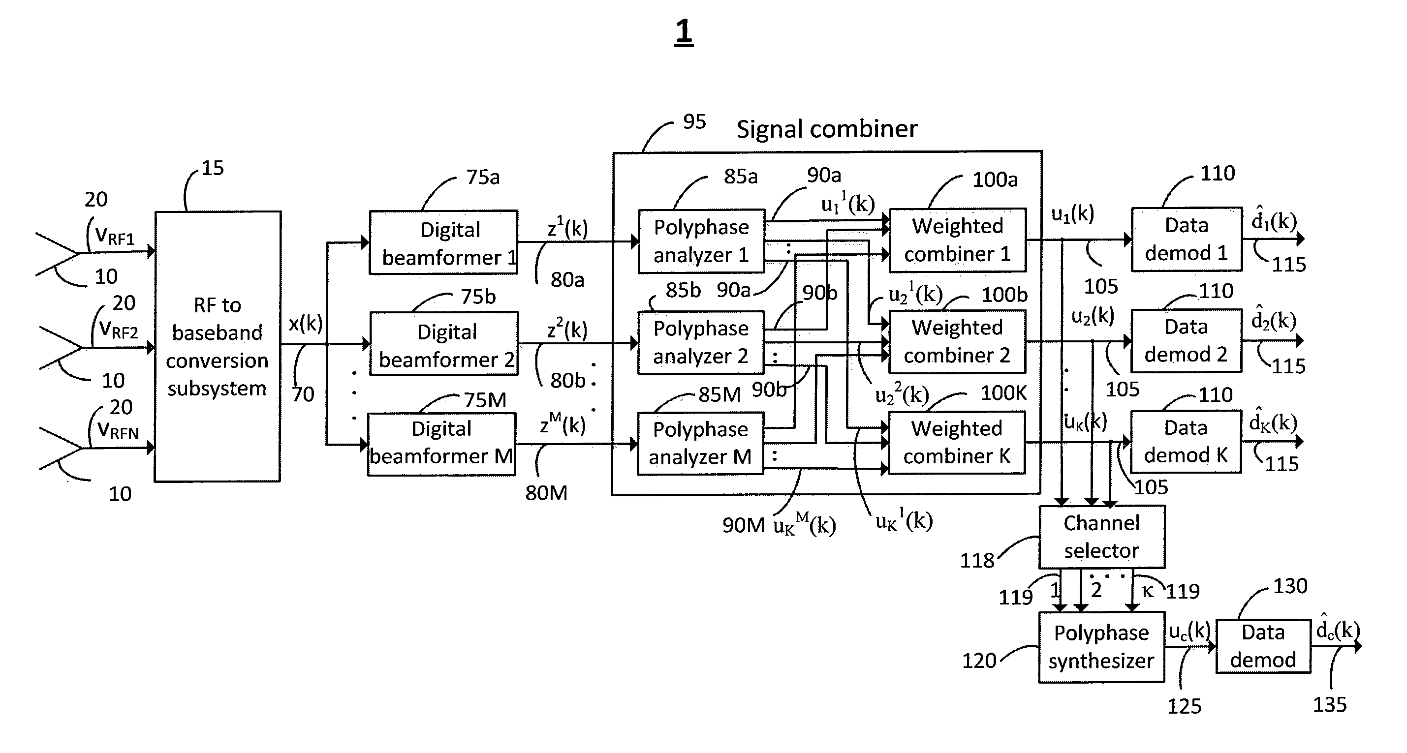
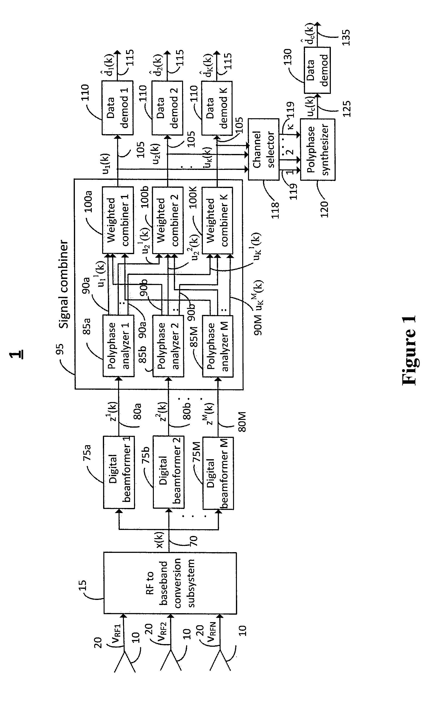
[0034]FIG. 1 shows one of the preferred embodiments of the invention for the MBA system 1 for the case of the Frequency Division Multiple Accessing (FDMA) communication system wherein the various users in the coverage area of the MBA are allocated different segments of the MBA system bandwidth. In the FDMA system the users in different geographical locations have different segments of the spectrum allocated to them and may experience different MBA antenna gain due to the introduction of the nulls in the direction of the interfere...


PUM


Abstract

Various embodiments described herein are directed to methods and systems for multibeam adaptive antenna architectures for recovering user signals in the coverage area of the antenna in the presence of interference sources. For example, various embodiments may utilize an architecture comprised of an array of antenna feeds, an RF to baseband conversion subsystem, a bank of digital beamformers, a channelization subsystem, a bank of weighted combiners, and a bank of demodulators for the demodulation and detection of user signals. The multiple beamformers introduce nulls in the direction of interference sources based on distinct adaptive algorithms for providing different antenna beam patterns after adaptation. Various other embodiments may utilize architecture for providing the directions of the interference sources or intentional jammers.

Description

BACKGROUND[0001]A multiple Beam Antenna (MBA) is a type of antenna system employed in the satellite applications and under normal operating mode has a field of view (FOV) that covers a section of the Earth's surface termed the coverage area. The MBA contains several feeds that illuminate a lens or a reflector system to produce multiple beams. The adaptive MBA is designed to combat interference sources including intentional jammers located anywhere within the desired area covered by the quiescent pattern of the antenna. This is accomplished by relatively high resolution afforded by a multibeam antenna with a relatively large aperture size and a significant number of beams providing the desired degrees of freedom in the adaptive nulling process. The outputs of the multiple beams are linearly combined in the MBA beamformer in an adaptive manner so as to introduce nulls in the direction of interference sources while minimizing the inevitable antenna gain reduction in any other direction...

Claims


Application Information

Patent Timeline
Patent Type & Authority Applications(United States)
IPC IPC(8): H04B7/08H04B1/12H04B1/10
CPCH04B7/086H04B7/0885H04B1/1081H04B1/123H04B7/0842H04B7/088H01Q3/2617
Inventor KUMAR, RAJENDRA
Owner KUMAR RAJENDRA
Why Eureka
Try Eureka