Pour-out member for discharging viscous fluid

a technology of viscous fluid and a member, which is applied in the field of pliable tubular containers, can solve problems such as liquid creeping, and achieve the effects of preventing container fouling and avoiding an increase in cos

Active Publication Date: 2014-11-13
TOYO SEIKAN GRP HLDG LTD
View PDF0 Cites 15 Cited by
  • Summary
  • Abstract
  • Description
  • Claims
  • Application Information

AI Technical Summary

Benefits of technology

[0015]The pour-out member of the present invention is the upper end surface or the top surface of the base member forming the pour-out port, and an important feature resides in that a hydrophobic layer comprising fine hydrophobic inorganic particles is selectively formed on a portion that serves as the pour-out port.
[0016]That is, the hydrophobic layer has not been formed on the portions (e.g., inner surface side that comes in contact with the liquid content) other than the upper end surface of the base member that serves as the pour-out port. Therefore, the container having the above pour-out port is capable of effectively eliminating such a problem that the hydrophobic layer splits and enters into the liquid contained in the container despite the cap is opened and closed repetitively.
[0017]Further, even when the cap is repetitively opened and closed with the hydrophobic layer being formed in a manner o

Problems solved by technology

However, the containers containing liquids are, without

Method used


Image

  • Pour-out member for discharging viscous fluid
  • Pour-out member for discharging viscous fluid
  • Pour-out member for discharging viscous fluid

Examples


example 1

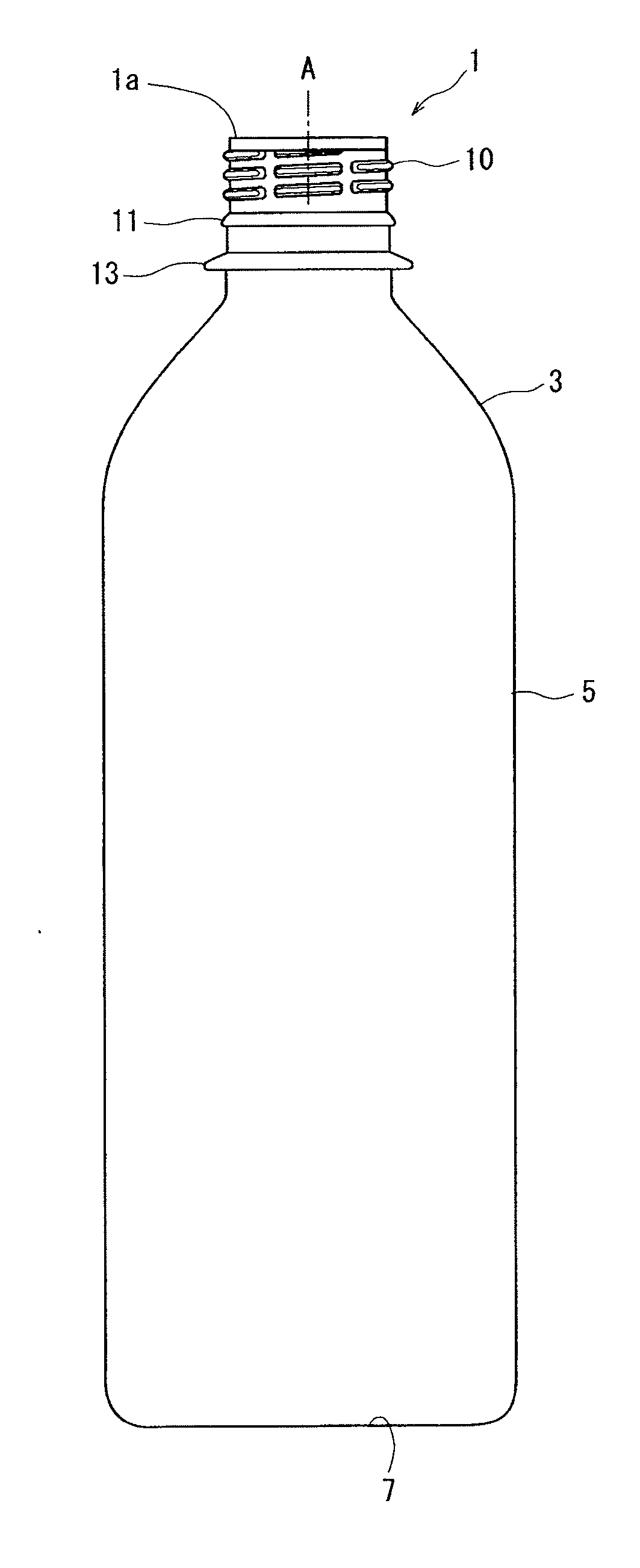
[0096]By using an injection-forming machine (NN75JS manufactured by Niigata Tekkosho Co.), a polyethylene terephthalate (PET) resin (RT543CTHP produced by Nihon Unipet Co.) that has been dried was injection-formed at a barrel setpoint temperature of 280° C. in a cycle time of 30 seconds to obtain an amorphous preform weighing 28 g (for a 500-ml PET bottle).

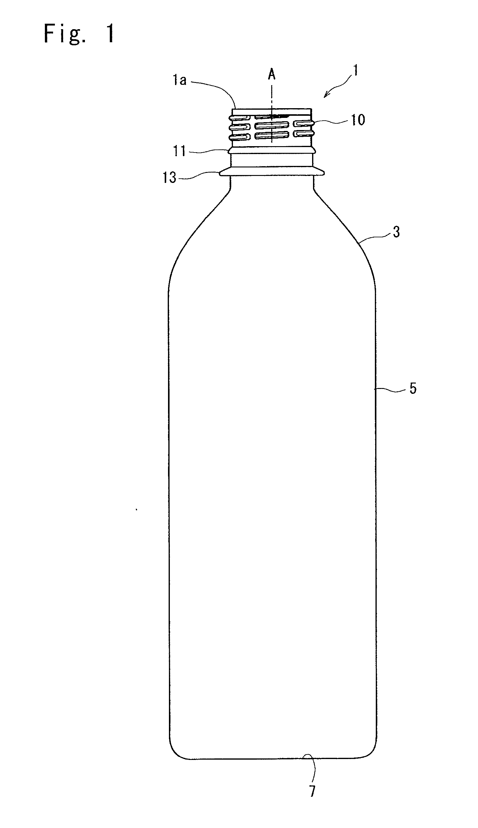
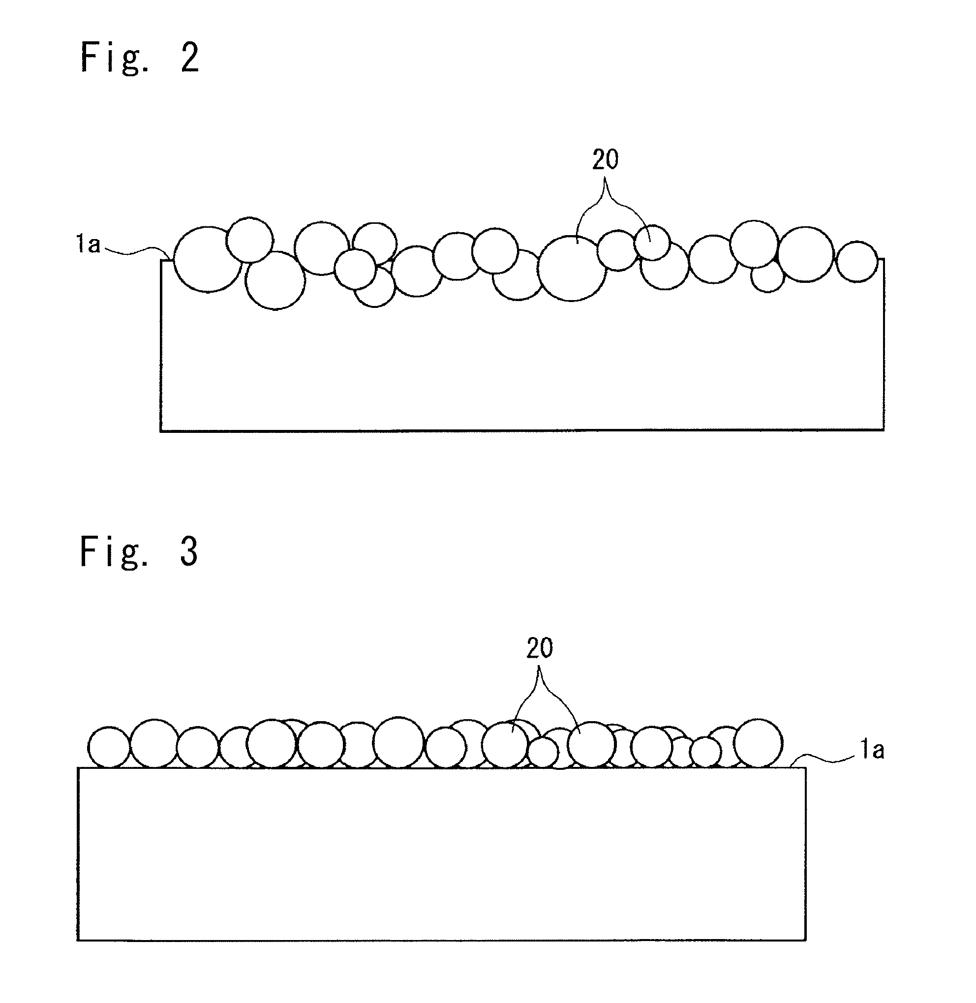
[0097]After formed, there was provided, as the lower mold (jig 60 for forming hydrophobic layer), an aluminum mold equipped with a band heater and having, in the upper surface thereof, a dent (recessed portion 63) of a diameter of 32 mm and a depth of 1.8 mm, and hydrophobic silica (RX300 produced by Nihon Aerosil Co.) was filled in the dent.

[0098]After filled, the whole lower mold was heated by the band heater at 60° C. As the upper mold, there was provided an aluminum mold capable of fixing the preform. The formed amorphous preform was fixed thereto with the nozzle portion facing downward, and the upper mold was pressed onto the...

example 2

[0102]0.4 Grams of a polyester resin (Bylon 200 produced by Toyobo Co.), 100 g of a methyl ethyl ketone (produced by Wako Junyaku Co.) and stirrer chips were put into a glass bottle, sealed therein, and were stirred by using a stirrer to a sufficient degree until the resin has dissolved. Thereafter, 3 g of hydrophobic silica (RX300 produced by Nihon Aerosil Co.) was added thereto, and was stirred by using the stirrer for 30 minutes. After stirred, the ultrasonic treatment was conducted for 30 minutes to obtain a homogeneous solution.

[0103]By using a bar coater, the obtained solution was applied onto one surface of a PET film of a thickness of 100 μm, and was dried in an oven heated at 100° C. for 2 minutes to obtain a film coated with the hydrophobic silica. A water droplet that was fallen on the film did not adhere thereto despite it was a small droplet proving water-repelling property.

[0104]A PET bottle was obtained in the same manner as in Example 1 but providing an aluminum bloc...

example 3

[0118]As the lower mold (jig 60 for forming hydrophobic layer), there was provided an aluminum mold equipped with a band heater and forming a dent (recessed portion 63) 40 mm in diameter and 1.8 mm in depth, and the dent was filled with a hydrophobic silica (R812S produced by Nihon Aerosil Co.).

[0119]After filled, the whole lower mold was heated at 100° C. by the band heater. As the upper mold, there was provided an aluminum mold capable of fixing the hinge cap. The hinge cap with polyethylene pull ring was fixed to the lower mold with the pour-out portion of the hinge cap facing downward, and the upper mold was pushed onto the lower mold with a pressure of 0.1 MPa for 2 seconds to press-adhere the hydrophobic silica onto the top surface of the pour-out portion of the hinge cap.

[0120]After press-adhered, the hydrophobic silica that has not been press-adhered was removed by blowing the air to obtain the hinge cap with pull ring. The obtained hinge cap was tested for the adhesiveness ...


PUM

PropertyMeasurementUnit
Grain sizeaaaaaaaaaa
Hydrophobicityaaaaaaaaaa
Thermoplasticityaaaaaaaaaa

Abstract

A pour-out member or, for example, a container has a pour-out port 1a through which a viscous fluid is discharged, wherein a hydrophobic layer of fine hydrophobic inorganic particles 20 is selectively formed on an upper end surface of a base member forming the pour-out port 1a. The hydrophobic layer formed on the pour-out port 1a of the pour-out member is not removed or broken through the repetitive use, and stably exhibits a function of preventing the liquid from creeping over extended periods of time.

Description

TECHNICAL FIELD[0001]This invention relates to a pour-out member having a pour-out port. More specifically, the invention relates to a pour-out member used for discharging liquids such as beverages and liquid seasonings or for pouring out such liquid contents, the pour-out member being, for example, a container, a cap with pour-out port, a nozzle, a spout or a container preform.BACKGROUND ART[0002]Pour-out members having pour-out port for discharging viscous liquids, such as containers, spouts fitted to caps with pour-out port, bag-like containers and paper containers, filler nozzles for filling foods, ink-jet nozzles and the like, have been widely used for a variety of kinds of applications such as industrial products, fittings for applying adhesives or solders, fittings used for experiments and equipment for inspection and medicinal uses. The pour-out ports of such pour-out members are made from various materials depending on the use, and many of the materials are plastics, glasse...

Claims


Application Information

Patent Timeline
IPC IPC(8): B65D23/08B32B37/24B05D5/00B32B37/14B05D1/18B32B37/00
CPCB65D23/0814B05D1/18B32B37/025B05D5/00B32B37/144B32B37/24B32B2307/73B32B2037/243B32B2311/00B32B2439/60B29C2059/028B29K2995/0093B32B3/08B32B5/16B65D23/06Y10T428/13B32B3/085B65D23/065B65D23/0828B65D47/40
Inventor AKUTSU, YOSUKEHORIUCHI, SHIGETOSHI
Owner TOYO SEIKAN GRP HLDG LTD
Why Eureka
Try Eureka