Honeycomb structure

a honeycomb and structure technology, applied in the field of honeycomb structure, can solve the problems of increasing the thickness of the alumina layer, not significantly increasing the contact potential, and undesirably heightening the pressure loss

Inactive Publication Date: 2006-12-28
IBIDEN CO LTD
View PDF12 Cites 76 Cited by
  • Summary
  • Abstract
  • Description
  • Claims
  • Application Information

AI Technical Summary

Benefits of technology

[0006] In the honeycomb structure of the invention, a ratio of the total sum of the cross section areas of the honeycombed faces of the honeycomb units perpendicular to the through holes to a cross section area of a honeycombed face of the honeycomb structure perpendicular to the through holes is preferably about 85% or more, and more preferably about 90% or more.

Problems solved by technology

A simple increase in the carried amount of the material having a high specific surface area, for example, active alumina, may, however, only increase the thickness of an alumina layer, while not significantly increasing the contact potential and undesirably heightening a pressure loss.

Method used


Image

  • Honeycomb structure
  • Honeycomb structure
  • Honeycomb structure

Examples


example 1

[0059] The process of example 1 mixed 40% by weight of γ-alumina particles (average particle diameter: 2 μm) as the inorganic particles, 10% by weight of silica alumina fibers (average fiber diameter: 10 μm, average fiber length: 100 μm, aspect ratio: 10) as the inorganic fibers, and 50% by weight of silica sol (solid content: 30% by weight) as the inorganic binder to give a mixture. The process added 6 parts by weight of methylcellulose as an organic binder and small amounts of a plasticizer and a lubricant with stirring to 100 parts by weight of the mixture and sufficiently kneaded the whole mixed composition. The mixed composition was extrusion molded by an extruder to a raw molded body.

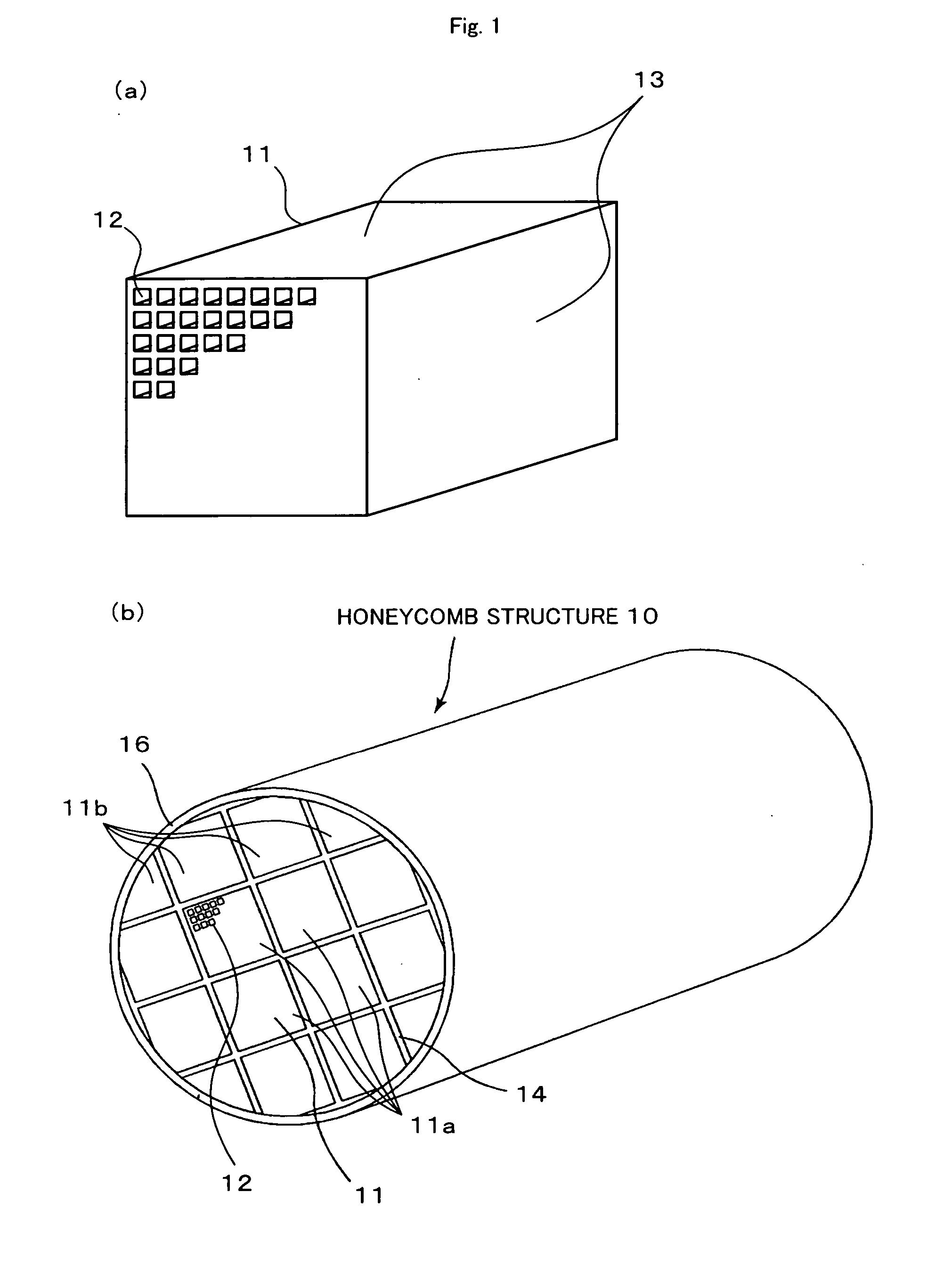
[0060] The raw molded body was sufficiently dried with a microwave dryer and a hot air dryer and was kept at 400° C. for 2 hours for degreasing. The degreased molded object was fired at 800° C. for 2 hours to give a square-pillar honeycomb unit 11 (34.3 mm×34.3 mm×150 mm) having a cell density of...

examples 2 to 7

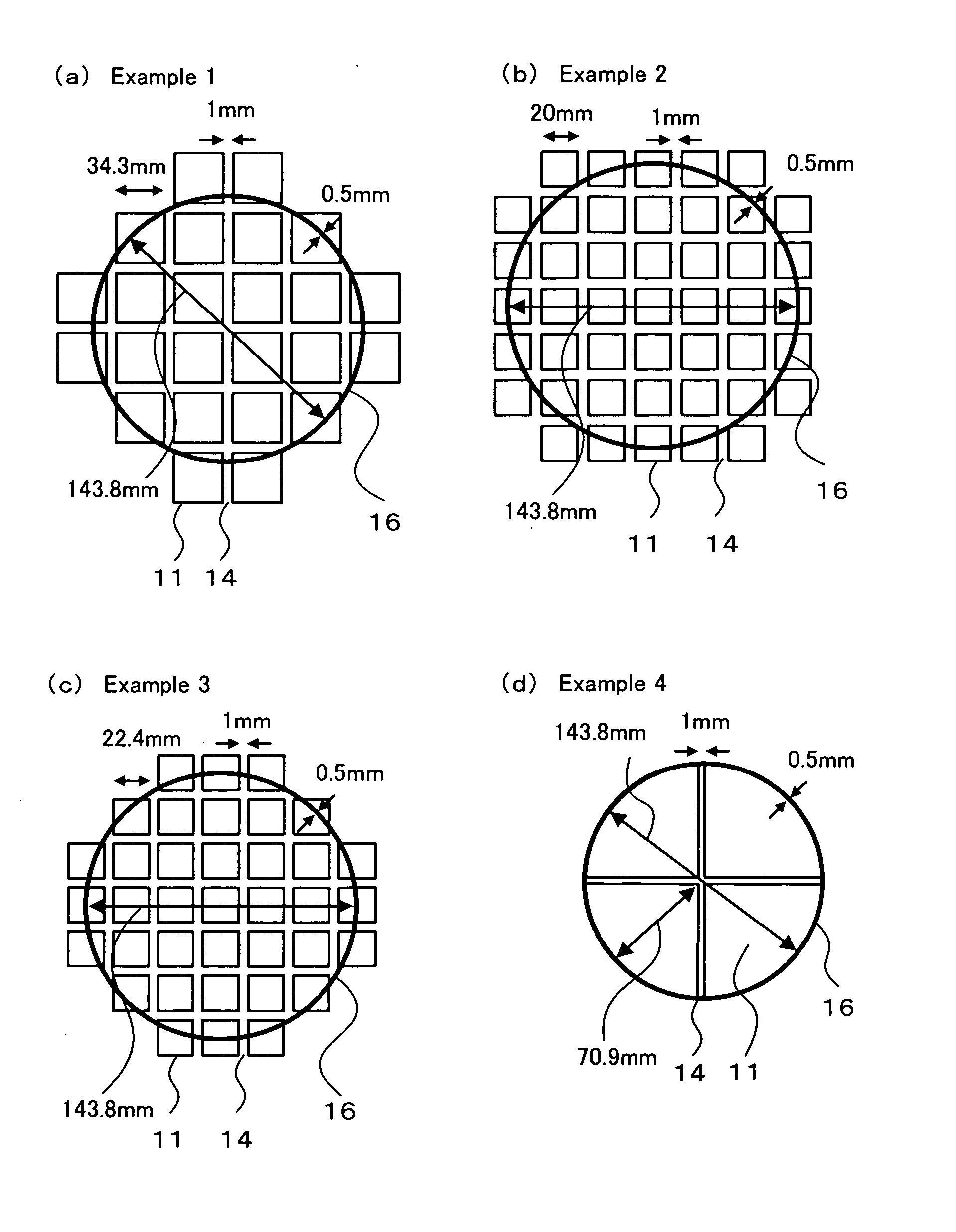
[0062] The honeycomb structures 10 were produced in the same manner as in the example 1 except for becoming the shapes shown in Table 1. The shapes of the honeycomb unit assemblies of the examples 2, 3 and 4 are respectively shown in FIGS. 3(b), (c) and (d), and the shapes of the honeycomb unit assemblies of the examples 5, 6 and 7 are respectively shown in FIG. 4(a), (b) and (c). In the example 7, the honeycomb structure 10 is integrally molded, and a joining process and a cutting process were not performed.

examples 8 to 14

[0063] The honeycomb units 11 were produced in the same manner as in the example 1 except for using titania particles (average particle diameter: 2 μm) as the inorganic particles and becoming the shapes shown in Table 1. Then, the honeycomb structures 10 were produced in the same manner as in the example 1 except for using the titania particles (average particle diameter: 2 μm) as the inorganic particles of the seal layer and coating layer. The shapes of the honeycomb unit assemblies of the examples 8 to 11 are respectively the same as those of FIGS. 3(a) to (d), and the shapes of the honeycomb unit assemblies of the examples 12 to 14 are respectively the same as those of FIG. 4(a) to (c). In the example 14, the honeycomb structure 10 is integrally molded.


PUM

PropertyMeasurementUnit
areaaaaaaaaaaa
surface roughness Rzaaaaaaaaaa

Abstract

A honeycomb structure 10 includes: multiple honeycomb units 11 having multiple through holes 12; and a seal layer 14 that joins adjacent honeycomb units 11 with each other via respective closed outer faces 13 of the honeycomb units 11 that are different from respective honeycombed faces of the honeycomb units 11. The honeycomb unit 11 includes at least inorganic particles, inorganic fibers and/or whiskers. A cross section area of a honeycombed face of the honeycomb unit perpendicular to the through holes 12 is about 5 to about 50 cm2, and the surface roughness Rz of the outer face 13 is about 5 to about 50 μm.

Description

BACKGROUND ART [0001] 1. Field of the Invention [0002] The invention relates to a honeycomb structure. [0003] 2. Description of the Related Art [0004] A honeycomb catalyst is generally used to convert the exhaust gas of vehicles. The honeycomb catalyst is conventionally manufactured by making a material of a high specific surface area, for example, active alumina, and a catalyst metal, for example, platinum, carried on the surface of an integral cordierite base honeycomb structure of low thermal expansion characteristics. An alkaline earth metal, such as Ba, is carried on the honeycomb structure as a NOx storage agent to treat NOx in an excess oxygen atmosphere of, for example, lean burn engines and diesel engines. The enhanced conversion performance is attained by improving the potential for bringing the exhaust gas into contact with the noble metal catalyst and the NOx storage agent. For this purpose, it is required to increase the specific surface area of the carrier while decrea...

Claims


Application Information

Patent Timeline
Patent Type & Authority Applications(United States)
IPC IPC(8): B32B3/12
CPCB01D46/2425Y10T428/24149B01D46/2451B01D46/2455B01D46/2459B01D53/9454B01D2046/2496B01D2255/102C04B38/0009C04B38/0016C04B2111/00793C04B2111/0081F01N3/0222F01N3/035F01N3/2828F01N2330/06F01N2330/30F01N2450/28B01D46/2429Y02T10/22C04B35/76Y02A50/20Y02T10/12B01D46/2498B01D46/2484B01D46/2478
Inventor OHNO, KAZUSHIGEKUNIEDA, MASAFUMIOGYU, KAZUTAKE
Owner IBIDEN CO LTD
Why Eureka
Try Eureka