Electronic device with rotatable stop plate

Active Publication Date: 2014-11-13
CLOUD NETWORK TECH SINGAPORE PTE LTD
View PDF6 Cites 0 Cited by
  • Summary
  • Abstract
  • Description
  • Claims
  • Application Information

AI Technical Summary

Benefits of technology

The present patent relates to an electronic device with rotatable stop plates. The technical effect of this invention is to improve the heat dissipation of the electronic device by allowing airflow generated by system fans to flow directly to the electronic modules, even when one of the power supply units is removed. This ensures optimal heat dissipation and prevents overheating of the electronic device.

Problems solved by technology

The other power supply unit in the chassis obtains less airflow, thereby the heat dissipation of the other power supply unit is less than optimal.

Method used


Image

  • Electronic device with rotatable stop plate
  • Electronic device with rotatable stop plate
  • Electronic device with rotatable stop plate

Examples


Embodiment Construction

[0009]The disclosure, including the accompanying drawings, is illustrated by way of example and not by way of limitation. It should be noted that references to “an” or “one” embodiment in this disclosure are not necessarily to the same embodiment, and such references mean “at least one.”

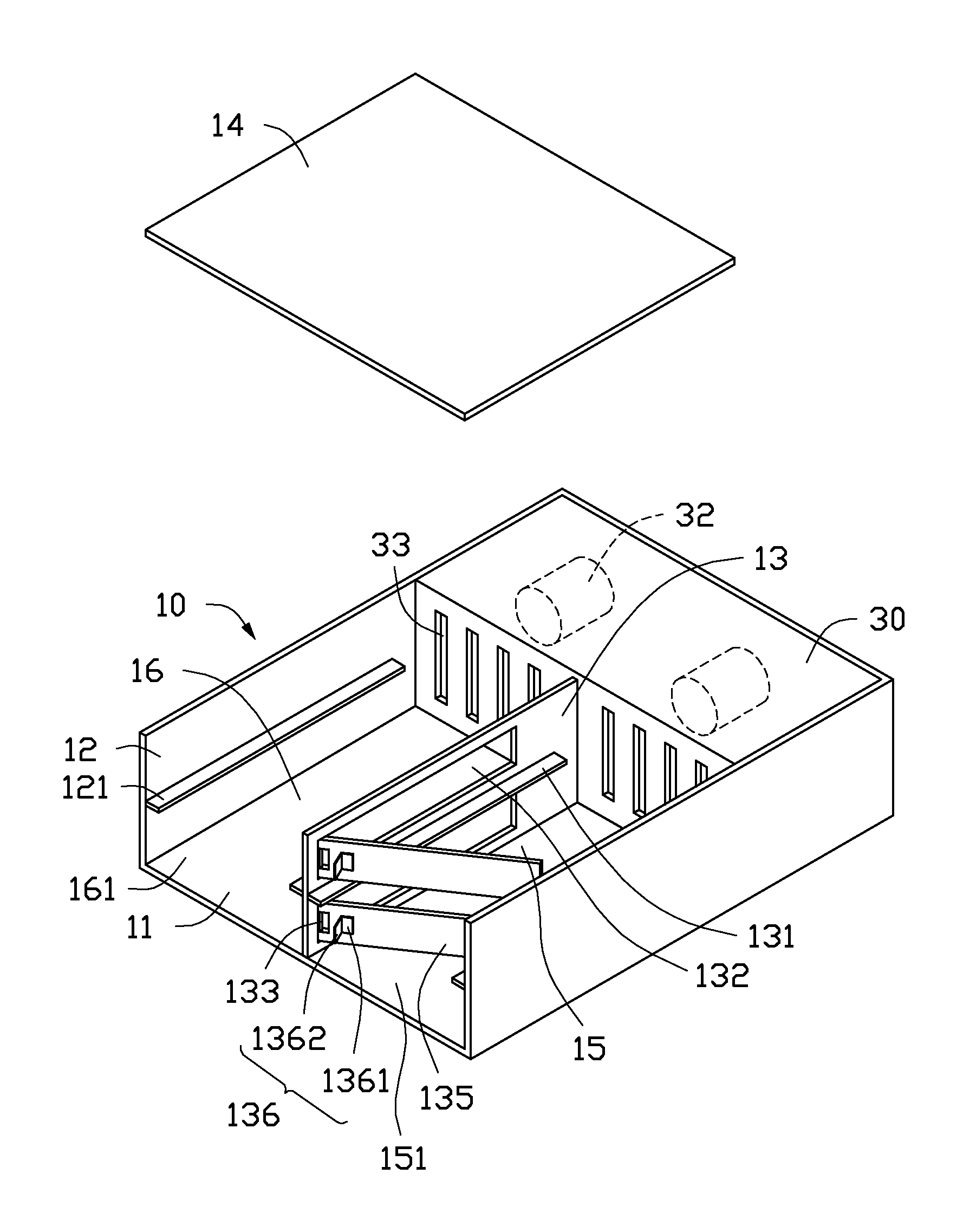
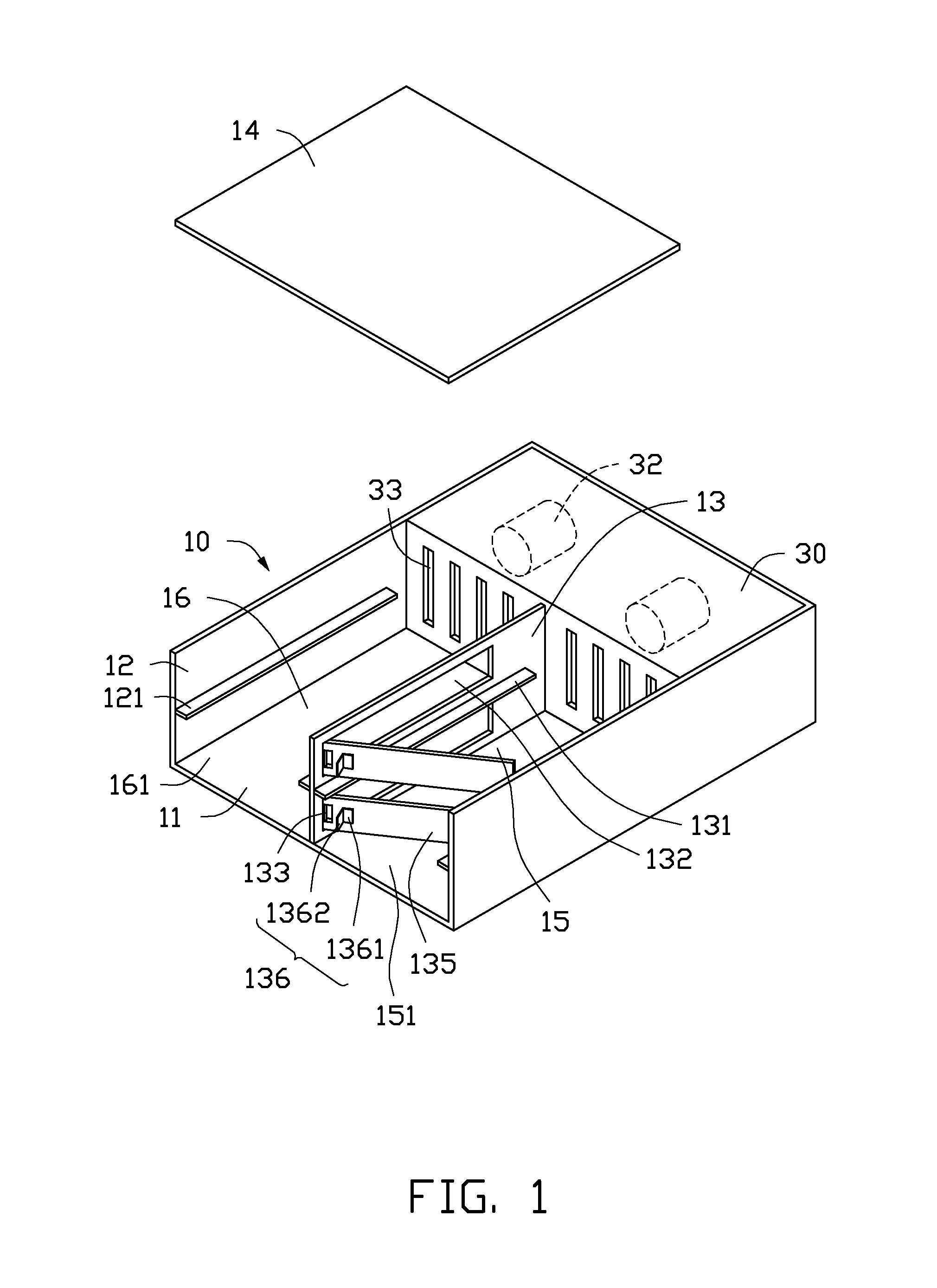
[0010]FIGS. 1 and 2 show an exemplary embodiment of an electronic device. The electronic device includes a receiving bracket 10, four electronic modules 20, and a casing 30 connected to a rear end of the receiving bracket 10. In the embodiment, the electronic modules 20 are power supply units.

[0011]The receiving bracket 10 includes a bottom plate 11, two side plates 12 perpendicularly extending up from opposite sides of the bottom plate 11, a partition plate 13 perpendicularly extending up from a middle of the bottom plate 11, and a top cover 14 connected to tops of the side plates 12 and partition plate 13. To see the inner structure of the receiving bracket 10 clearly, the top cover 14 is placed ab...


PUM


Abstract

An electronic device includes a receiving bracket and two electronic modules. The receiving bracket includes a partition plate to divide the receiving bracket into a first receiving space and a second receiving space. Each of the first receiving space and second receiving space includes an outlet located at an end of the receiving bracket. The partition plate defines a through slot. A stop plate is pivotably connected to an end of the through slot near the outlets. Two resilient tabs are formed on opposite sides of the stop plate, and respectively face the first receiving space and second receiving space. The electronic modules are received in the first receiving space and second receiving space, and deform the resilient tabs.

Description

BACKGROUND [0001]1. Technical Field[0002]The present disclosure relates to an electronic device with rotatable stop plates.[0003]2. Description of Related Art[0004]In an electronic device, two power supply units may be mounted in a chassis of the electronic device from up and down. If one of the power supply units is taken away, airflow from system fans will flow out of the chassis from the space once occupied by the power supply unit taken away. The other power supply unit in the chassis obtains less airflow, thereby the heat dissipation of the other power supply unit is less than optimal.BRIEF DESCRIPTION OF THE DRAWINGS [0005]Many aspects of the present embodiments can be better understood with reference to the following drawings. The components in the drawings are not necessarily drawn to scale, the emphasis instead being placed upon clearly illustrating the principles of the present embodiments. Moreover, in the drawings, all the views are schematic, and like reference numerals...

Claims


Application Information

Patent Timeline
IPC IPC(8): H05K7/12
CPCH05K7/12H05K7/20909
Inventor HU, JIN-JIASHU, TENG-YUAN
Owner CLOUD NETWORK TECH SINGAPORE PTE LTD
Why Eureka
Try Eureka