Tool changing mechanism for machine tool

a tool changer and tool technology, applied in the field of machine tools, can solve the problems that the tool changer or tool changing mechanism of the machine tool does not provide a stabilizing structure or mechanism, and achieve the effect of stably, smoothly replacing and changing the tool members

Inactive Publication Date: 2014-11-20
KUGI TECH CORP
View PDF9 Cites 8 Cited by
  • Summary
  • Abstract
  • Description
  • Claims
  • Application Information

AI Technical Summary

Benefits of technology

[0008]The primary objective of the present invention is to provide a machine tool including a tool changer or tool changing mechanism for suitably and stably and smoothly replacing a

Problems solved by technology

However, the typical tool changers or tool changing mechanisms for machine tools failed to provide a stabilizing structure or mechanism

Method used


Image

  • Tool changing mechanism for machine tool
  • Tool changing mechanism for machine tool
  • Tool changing mechanism for machine tool

Examples


Embodiment Construction

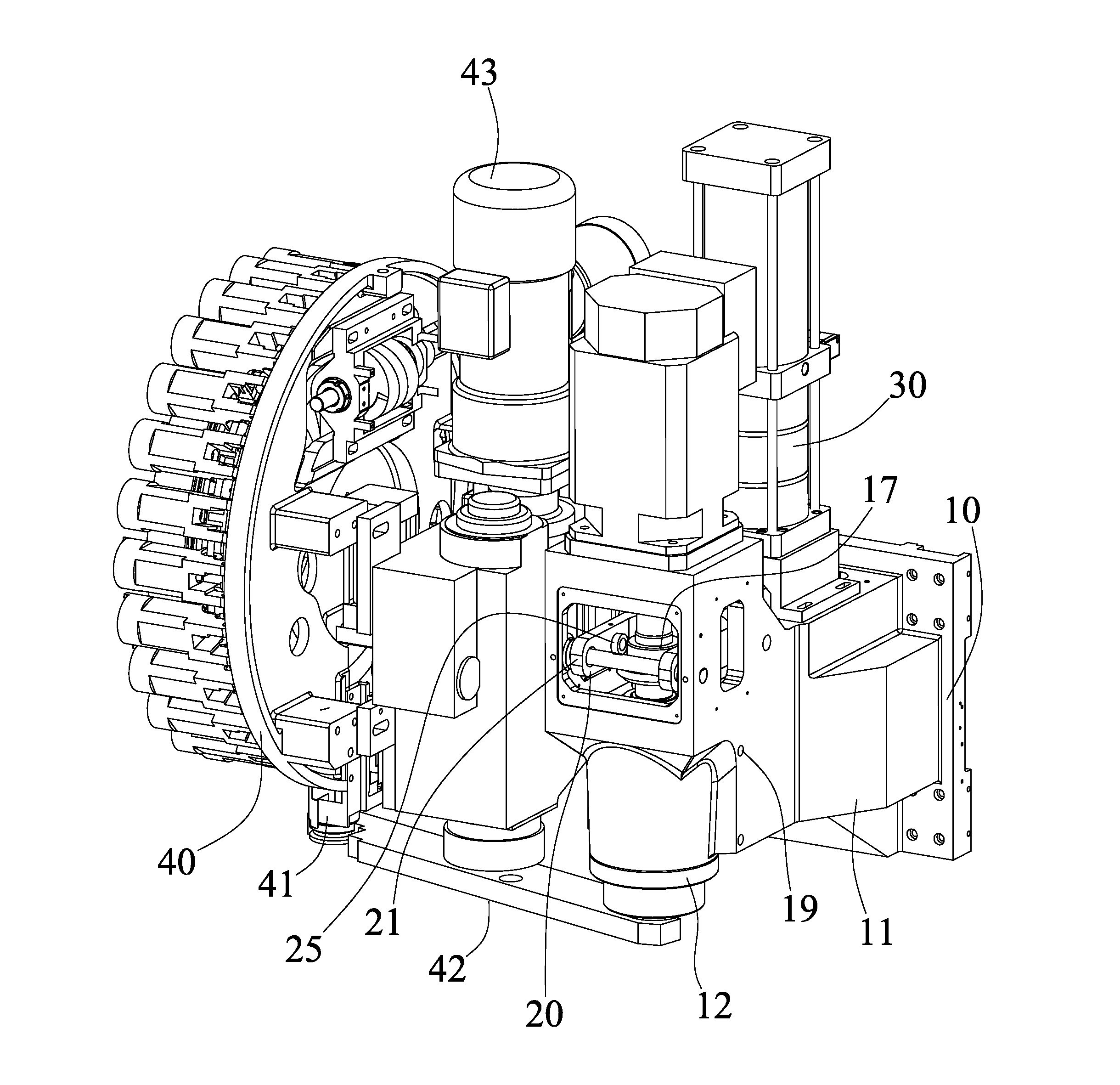
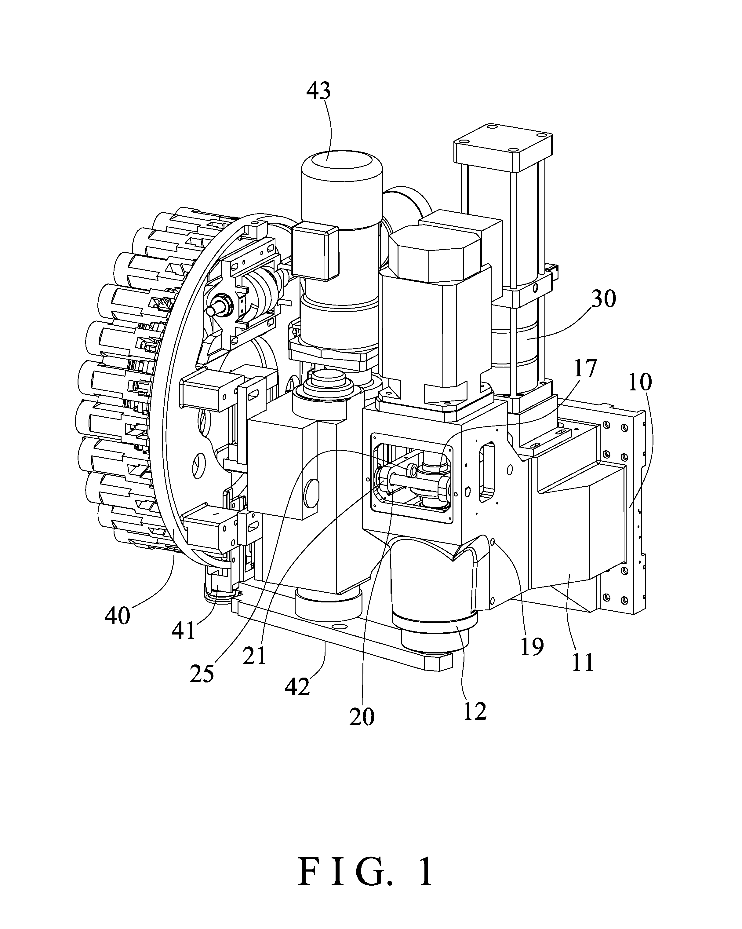
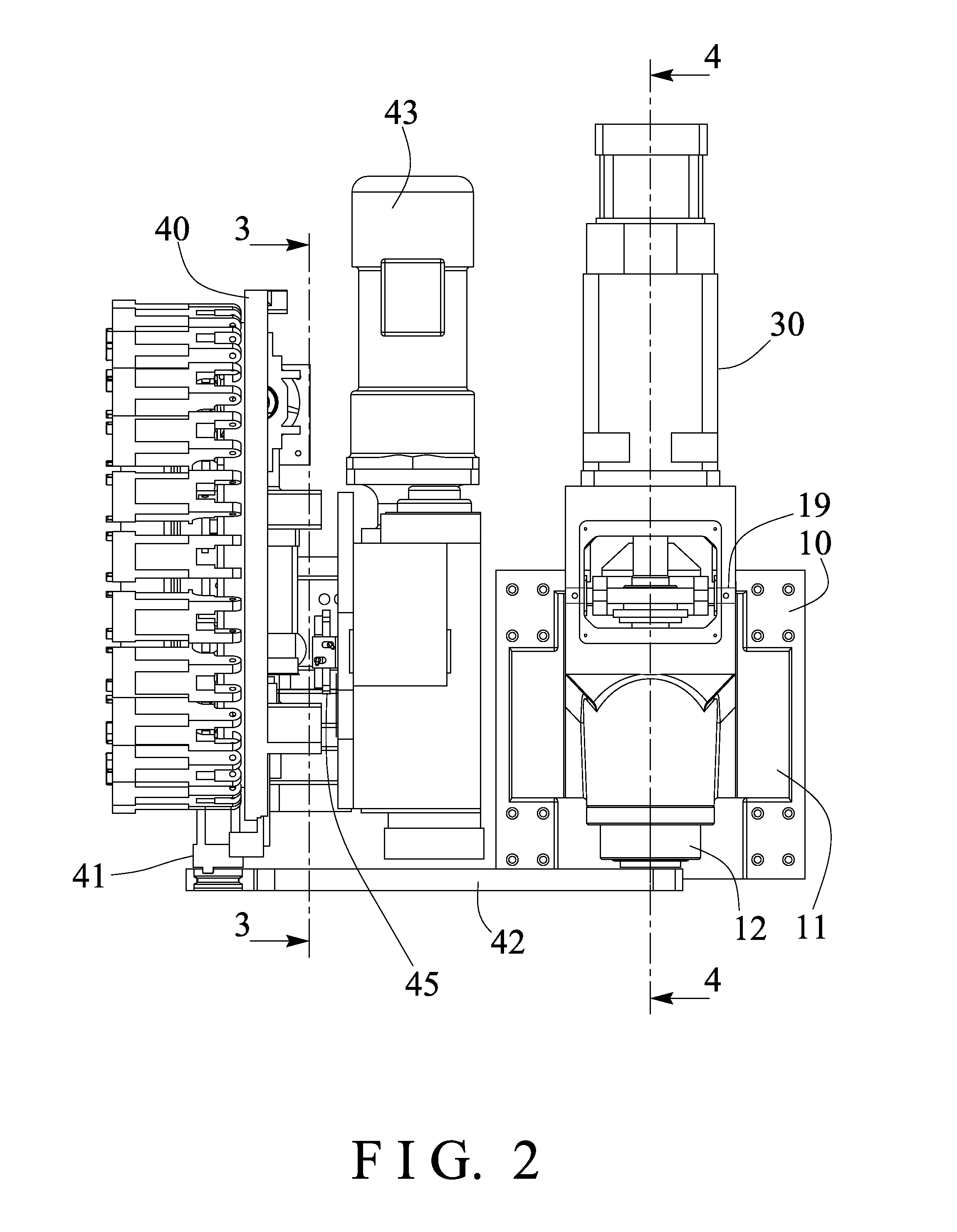
[0023]Referring to the drawings, and initially to FIGS. 1-4, a machine tool in accordance with the present invention comprises a machine body or column or stand 10 including a straight guide or guide rail or head or arm or support or receptacle 11 provided and attached or mounted or secured or supported on the stand 10 and extended forwardly from the stand 10, a working spindle 12 pivotally or rotatably attached or mounted or secured or disposed or engaged in the receptacle 11 (FIGS. 4, 6) with one or more bearing members 13 (FIG. 6) and having a bore 14 formed therein, and having an engaging hole 15 formed therein, such as formed in the lower or bottom portion thereof and communicating with the bore 14 thereof for receiving or carrying or supporting or engaging with a working tool member or element 90 therein.

[0024]As shown in FIG. 6, a spring biased gripping or chuck device 16 is slidably received or engaged in the bore 14 of the working spindle 12 for selectively gripping or gras...


PUM


Abstract

A machine tool includes a receptacle extended from a stand, a working spindle rotatably attached to the receptacle and having a chuck device for grasping and releasing a tool member from the working spindle, a follower slidably attached onto the working spindle for actuating the chuck device to selectively grasp or release the tool member, a lever arm having one end pivotally attached to the receptacle with an axle, an actuator attached to the lever arm for actuating the follower to operate the chuck device to grasp and to release the tool member, and a driving device includes a piston for moving the lever arm and the actuator to actuate and move the chuck device to release the tool member.

Description

BACKGROUND OF THE INVENTION[0001]1. Field of the Invention[0002]The present invention relates to a machine tool, and more particularly to a machine tool including a tool changer or tool changing mechanism for suitably and stably and smoothly replacing and changing tool members or elements to a working spindle and for allowing the tool members or elements to be stably and smoothly and effectively replaced and changed with each other.[0003]2. Description of the Prior Art[0004]Typical machine tools comprise a disc or tool carrier or cartridge including a number of adapters or tool mounts for removably and changeably carrying or supporting tool members thereon, and for selectively or changeably supplying or feeding or fitting the selected tool members to the working spindle of the typical machine tool for changing the tool members from one to the other.[0005]For example, U.S. Pat. No. 4,776,081 to Okunishi et al., U.S. Pat. No. 5,762,594 to Hoppe, U.S. Pat. No. 6,102,840 to Xiao, U.S. P...

Claims


Application Information

Patent Timeline
IPC IPC(8): B23Q3/157B23Q3/155
CPCB23Q3/15513B23Q3/15753B23Q3/1554B23Q3/15553B23Q3/15713B23Q2003/155418B23Q2003/155428Y10T409/309464Y10T483/1733Y10T483/1748Y10T483/1752Y10T483/176
Inventor LIU, CHE SEN
Owner KUGI TECH CORP
Why Eureka
Try Eureka