Tether for submerged moving vehicle

a moving vehicle and tether technology, applied in the field of tethers, can solve the problems of low amount of generated electrical energy from a single turbine of a certain size, cumbersome and expensive manufacturing, handling and operation of fixed stream-driven power plant systems, and more complex and costly installation and handling, so as to achieve more efficient and durable operation and handling of the submerged device.

Active Publication Date: 2014-12-04
MINESTO
View PDF13 Cites 3 Cited by
  • Summary
  • Abstract
  • Description
  • Claims
  • Application Information

AI Technical Summary

Benefits of technology

[0005]In view of the above-mentioned and other drawbacks of the prior art, a general object of the present invention is to provide an improved tether for connecting a device submerged in liquid, such as a stream-driven vehicle of a submersible power plant system, to a support structure, wherein the tether provides more efficient and durable operation and handling of the submerged device.

Problems solved by technology

A drawback with stationary stream-driven power plant systems, however, is that the amount of generated electrical energy from a single turbine of a certain size is low, which may be compensated by increasing the number of turbines, or increasing the effective area of the turbines.
Those solutions, however, lead to cumbersome and expensive manufacturing, handling and operation of the fixed stream-driven power plant systems.
This also leads to more complex and costly installation and handling.
Moreover, access to such high flow speed locations is relatively limited.
One drawback associated with current solutions of power plant systems comprising a stream-driven vehicle is that the drag force acting on the power plant system reduces the efficiency of the electrical energy generation.
An additional consideration of stream-driven submersible power plant systems is that they are mounted and arranged to operate in a submerged location, being difficult to access.
Hence, handling and servicing of those systems is cumbersome.
Accordingly, currently available, or known, stream-driven submersible power plant systems, and parts thereof, limit the maximal capability of efficiently generating electrical energy.

Method used


Image

  • Tether for submerged moving vehicle
  • Tether for submerged moving vehicle
  • Tether for submerged moving vehicle

Examples


Embodiment Construction

[0047]In the drawings, similar, or equal elements are referred to by equal reference numerals. The drawings are merely schematic representations, not true to scale and should not be considered as limiting the scope of the invention.

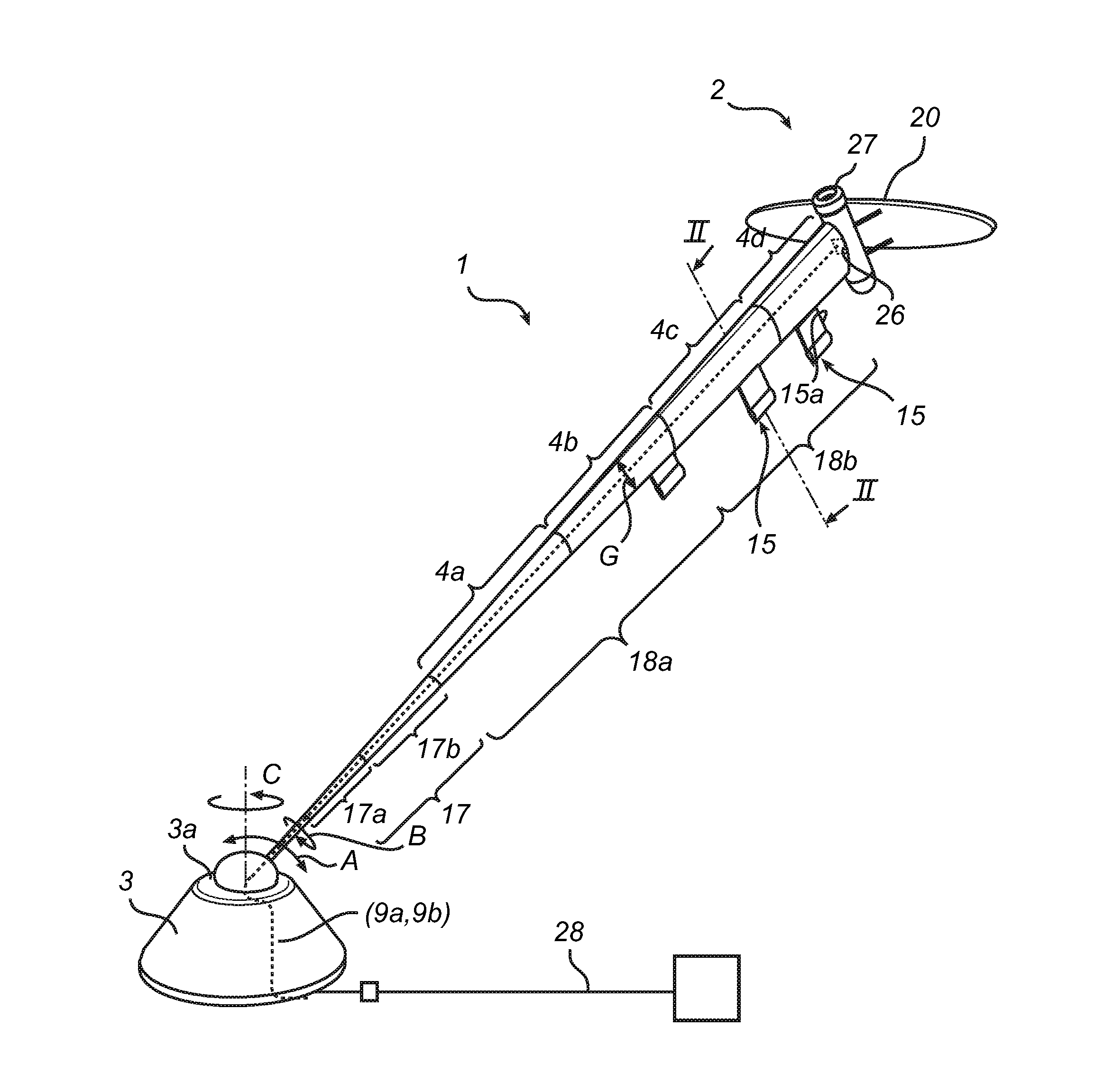
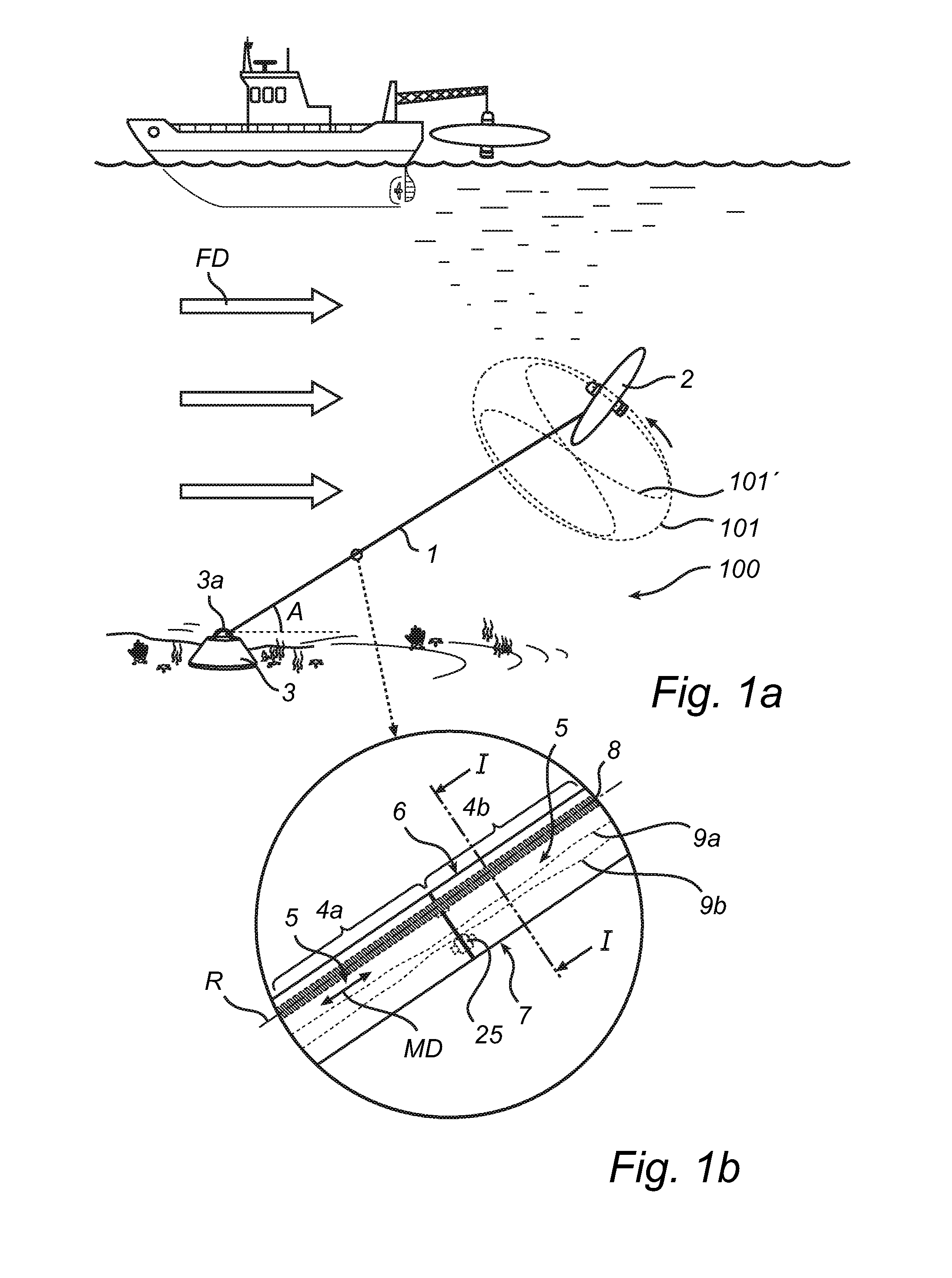
[0048]In FIG. 1a, a schematic side view of an exemplifying embodiment of the tether 1 securing and supporting a submerged and moving stream-driven vehicle 2 to a support structure 3 arranged at the seabed, is illustrated. The tether 1, the vehicle 2, and the support structure 3 essentially form a stream-driven submerged power plant system 100, wherein electrical energy is generated in the vehicle 2 by a turbine and generator. A liquid, typically water, has a flow direction FD, wherein the vehicle utilizes the energy of the flowing water in order to move along a submerged trajectory 101 or 101′, such as a circulating, and / or endless trajectory. The trajectory may have an annular or circular shape, as illustrated by 101. The trajectory may further be formed...


PUM


Abstract

The present invention relates to a tether for connecting a moving device submerged in liquid to a support structure, e.g. a submersible power plant comprising a stream-driven vehicle provided with at least one turbine for generation of electrical energy. The tether extends in a main direction, and at least a tether portion of the tether comprises a tensile force bearing portion extending in the main direction of the tether, wherein the tether portion is arranged to strive to self-align in relation to a relative flow direction of the liquid during use.

Description

FIELD OF THE INVENTION[0001]The present invention relates to a tether for connecting a moving device submerged in liquid, such as water, to a support structure. For example, the moving device may be a stream-driven vehicle of a submersible power plant, which vehicle is provided with at least one turbine for generation of electrical energy.BACKGROUND[0002]Streams and ocean currents, such as tidal stream flows, provide a predictable and reliable source of energy that can be used for generating electrical energy. Stationary, or fixed, power plant systems are known which are submerged and secured in relation to the stream or flow, wherein a turbine is used to generate electrical energy from the flow velocity of the stream. A drawback with stationary stream-driven power plant systems, however, is that the amount of generated electrical energy from a single turbine of a certain size is low, which may be compensated by increasing the number of turbines, or increasing the effective area of ...

Claims


Application Information

Patent Timeline
Patent Type & Authority Applications(United States)
IPC IPC(8): B63B21/50F03B13/10
CPCB63B21/50B63B2205/00F03B13/10F03B17/06F03B17/061F05B2240/917F05B2240/97Y02E10/20Y02E10/30F05B2240/9174B63B21/663
Inventor QUAPPEN, ARNEMARZELIUS, OLOF
Owner MINESTO
Why Eureka
Try Eureka