Guide features for a cable backplane system

a technology of backplane system and guide feature, which is applied in the direction of cable termination, electrical apparatus construction details, casings/cabinets/drawers, etc., can solve the problems of large number of cable assemblies, signal integrity inherently degrades, and the packaging of large numbers of cable assemblies is difficul

Active Publication Date: 2014-12-11
TYCO ELECTRONICS LOGISTICS AG (CH)
View PDF3 Cites 16 Cited by
  • Summary
  • Abstract
  • Description
  • Claims
  • Application Information

AI Technical Summary

Benefits of technology

[0005]In one embodiment, a cable backplane system includes a backplane having a plurality of openings therethrough and a plurality of mounting blocks on a front of the backplane with guide holes proximate to the openings. A cable rack is coupled to a rear of the backplane. The cable rack includes a tray having a frame surrounding a raceway and spacers coupled to the tray that have guide pins received in corresponding guide holes in the backplane. Cable connector assemblies are held by the tray and have a plurality of cables extending between at least two cable connectors with the cables routed in the raceway and the cable connectors positioned between and supported by corresponding spacers on opposite sides of the cab...

Problems solved by technology

As the density of the systems increase and requirements for high speed lines increase, the printed circuit boards continue to become larger and the signal integrity inherently degrades as the signals travel further along the entire channel.
However, packaging of large numbe...

Method used


Image

  • Guide features for a cable backplane system
  • Guide features for a cable backplane system
  • Guide features for a cable backplane system

Examples


Embodiment Construction

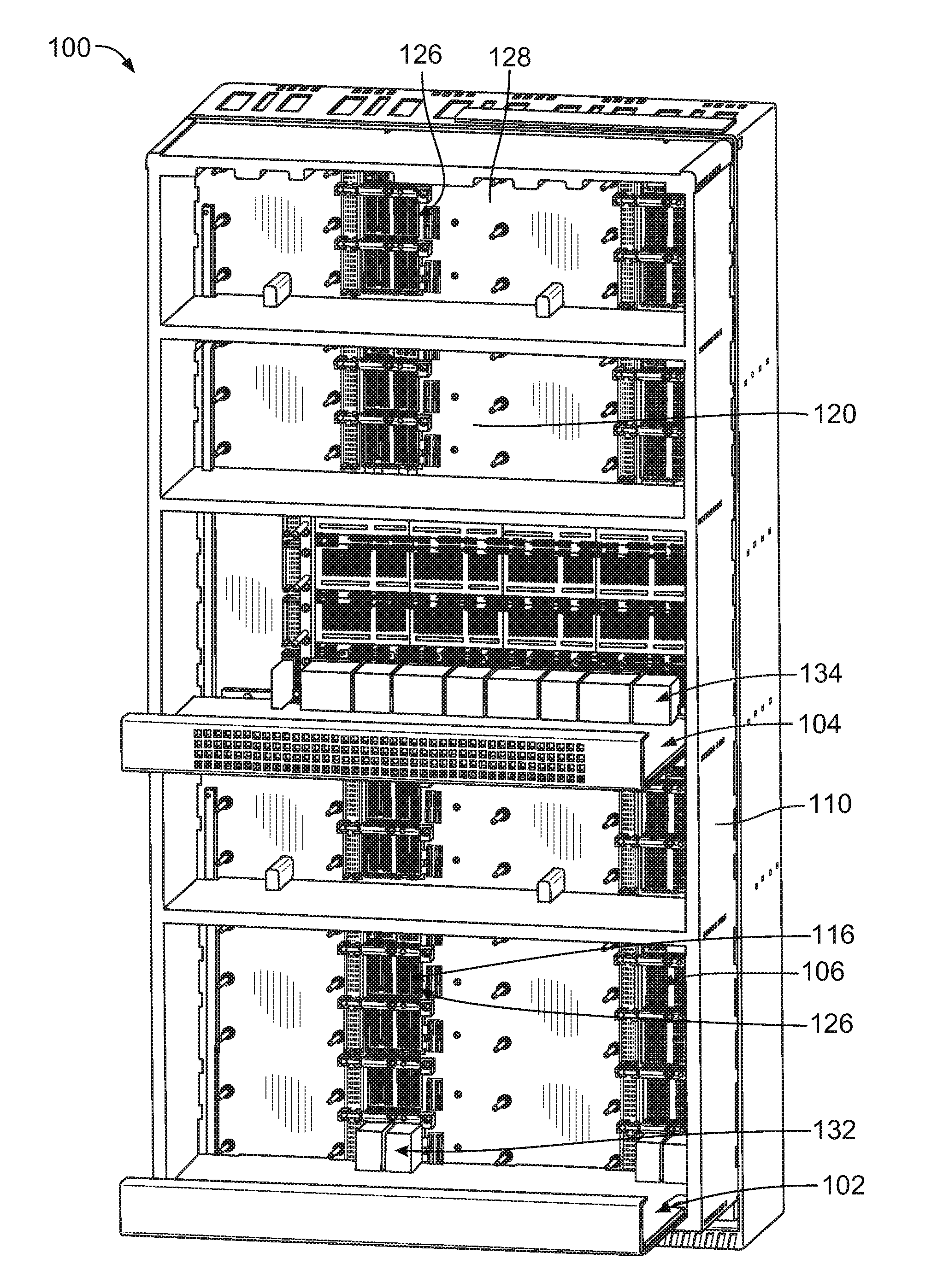
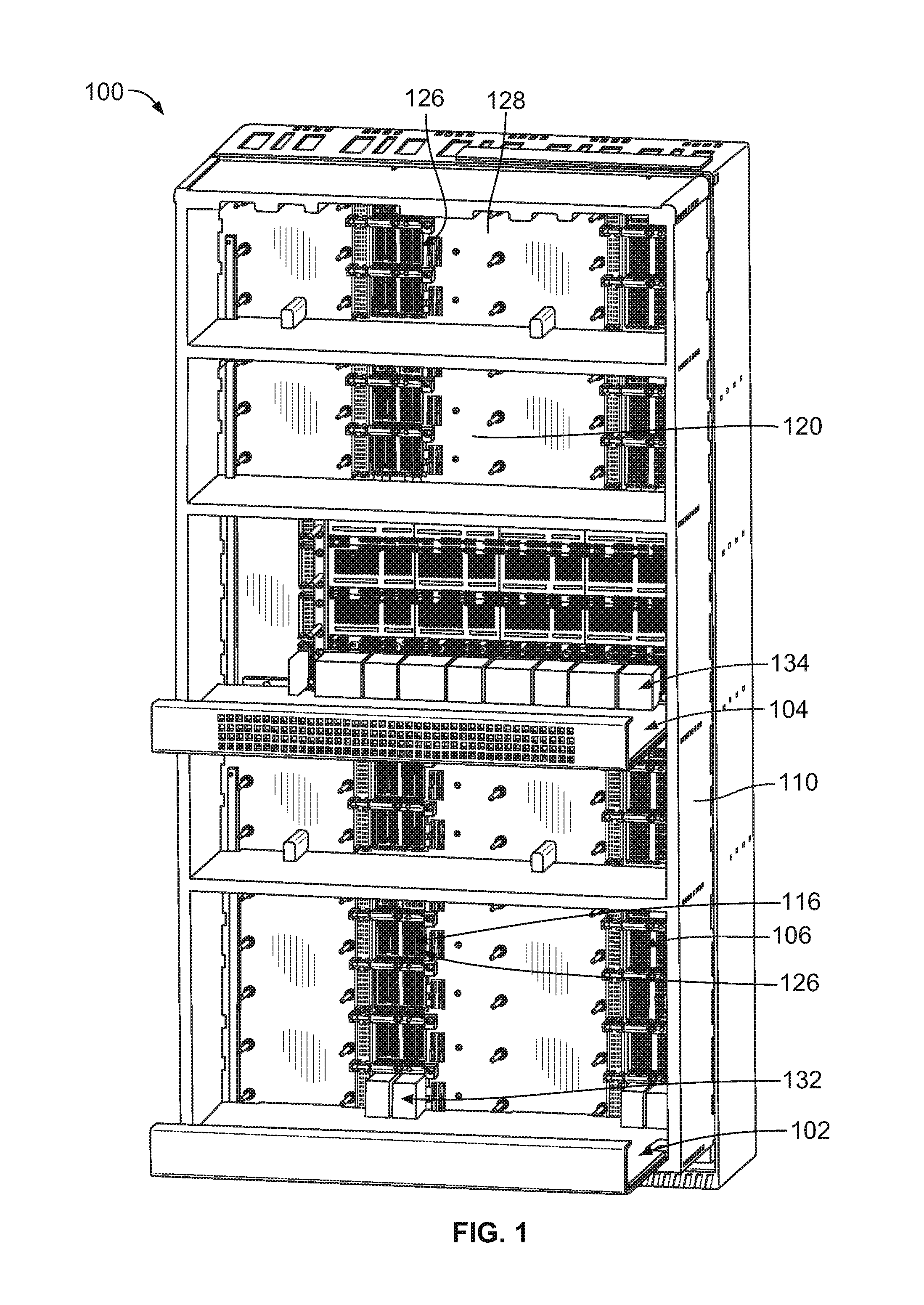
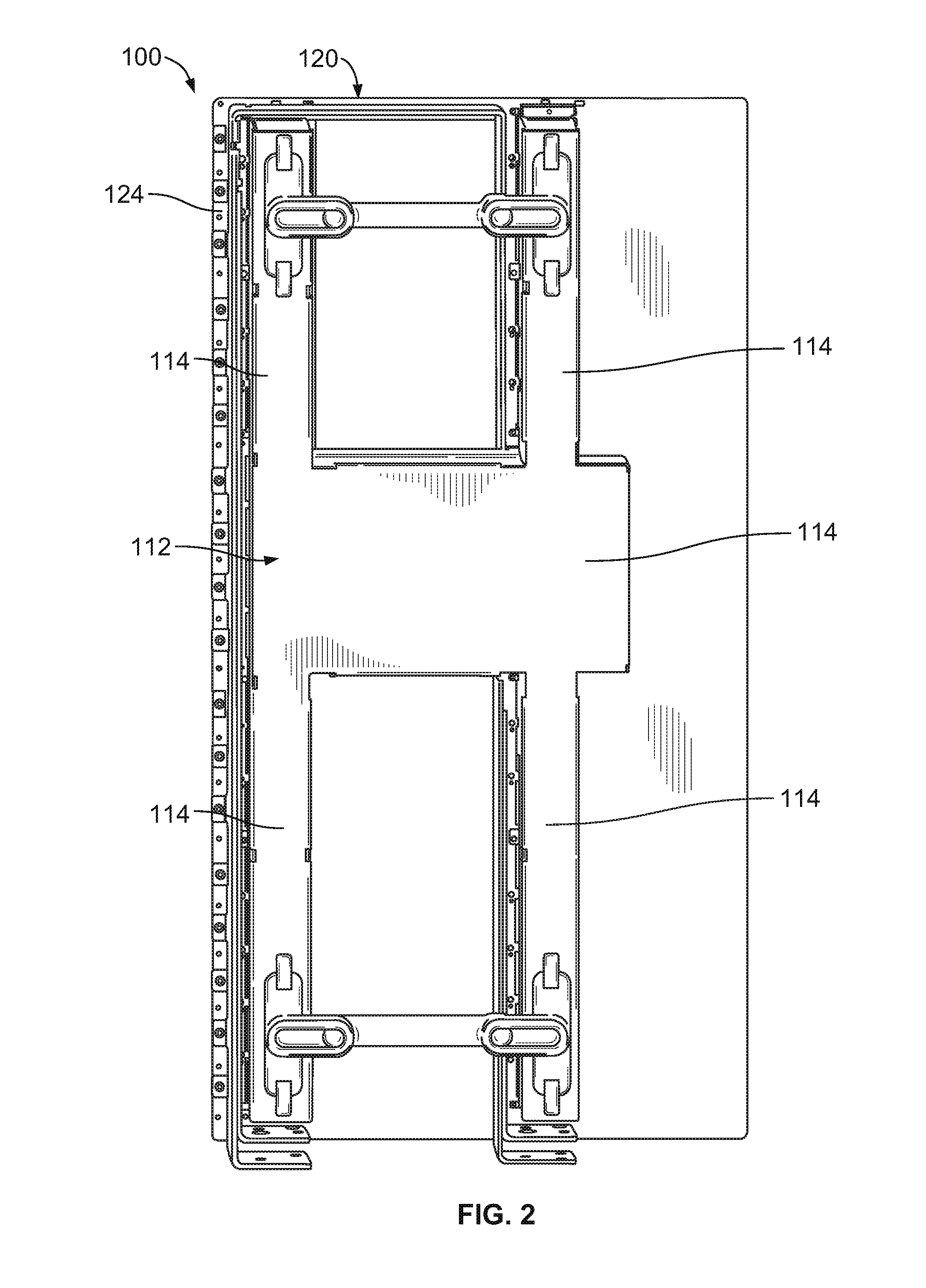
[0021]FIG. 1 is a front perspective view of a cable backplane system 100 formed in accordance with an exemplary embodiment. FIG. 2 is a rear perspective view of the cable backplane system 100. The cable backplane system 100 is used in a data communication application, such as a network switch. The cable backplane system 100 interconnects line cards 102 and switch cards 104 using cable connector assemblies 106. The cable backplane system 100 may be used to interconnect with other types of connectors and / or cards, such as daughtercards, in other embodiments.

[0022]The cable connector assemblies 106 include cable connectors 116 that are interconnected by cables within the cable backplane system 100. The cable connector assemblies 106 eliminate interconnections via traces of a circuit board, such as a backplane circuit board. The cable connector assemblies 106 have improved signal performance along the signal paths between various connectors of the cable backplane system 100 as compared ...


PUM


Abstract

A cable backplane system includes a backplane having a plurality of openings therethrough. A cable rack is coupled to a rear of the backplane, which includes a tray and spacers coupled to the tray that have guide pins. Cable connector assemblies are held by the tray. Removable dust caps are coupled to corresponding cable connectors each having a distal end and guide walls extending therefrom that guide mating of the cable rack with the backplane. The distal end of each dust cap is received in a corresponding opening in the backplane. The guide walls guide the cable rack relative to the backplane such that the guide pins of the spacers are aligned with guide holes of the backplane and such that the cable connectors are aligned with the openings of the backplane. The removable dust caps are removed after the cable rack is coupled to the backplane.

Description

BACKGROUND OF THE INVENTION[0001]The subject matter herein relates generally to guide features for a cable backplane system.[0002]Communication systems, such as network systems, servers, data centers, and the like, use large printed circuit boards, known as backplanes, to interconnect midplanes, daughtercards, line cards and / or switch cards. The communication systems use high speed differential connectors mounted to the backplane and high speed differential connectors mounted to the line cards and switch cards to transmit signals therebetween. The backplane interconnects the various connectors using traces along the circuit board.[0003]As the density of the systems increase and requirements for high speed lines increase, the printed circuit boards continue to become larger and the signal integrity inherently degrades as the signals travel further along the entire channel. At least some systems have replaced the traditional backplanes with cable assemblies. However, packaging of larg...

Claims


Application Information

Patent Timeline
IPC IPC(8): H02G3/10
CPCH02G3/105H04Q1/06H04Q1/15H05K7/1449H02B11/00H04Q1/00H05K5/00
Inventor SECHRIST, JOSHUA TYLERRITTER, CHRISTOPHER DAVIDLEHMAN, NATHAN GLENNCOSTELLO, BRIAN PATRICKNICHOLS, ROBERT PAUL
Owner TYCO ELECTRONICS LOGISTICS AG (CH)
Why Eureka
Try Eureka