
Printer and printing method

Active Publication Date: 2014-12-11
BROTHER KOGYO KK
View PDF7 Cites 5 Cited by
  • Summary
  • Abstract
  • Description
  • Claims
  • Application Information

AI Technical Summary

Benefits of technology

The present invention provides a printer and printing method that can cut a printed matter when multiple printed matters are produced while sequentially incrementing a print identifier at the cutting position. This improves operator convenience.

Problems solved by technology

Nevertheless, according to the prior art, in a case where a plurality of printed matter is produced while incrementing a print identifier using various modes as described above, no particular consideration is given to the cutting settings related to the plurality of printed matter.
That is, only a setting whereby the print-receiving tape is cut after the entire plurality of printed matter has been continually formed (the entire plurality of printed matter has been formed as an integrated object) is prepared in a fixed manner, resulting in low convenience for the operator.

Method used


Image

  • Printer and printing method
  • Printer and printing method
  • Printer and printing method

Examples


Embodiment Construction

[0027]The following describes an embodiment of the present disclosure with reference to accompanying drawings.

Outer Appearance Configuration of Print Label Producing Apparatus

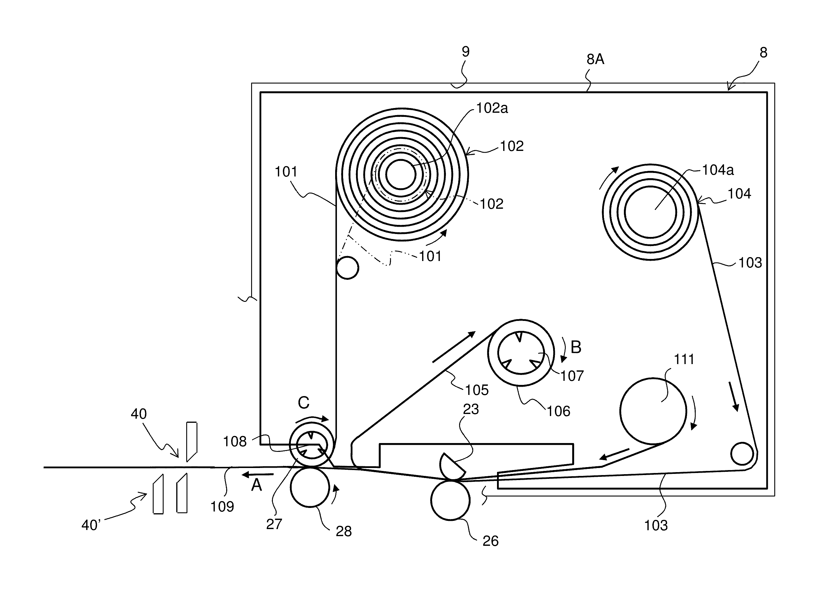
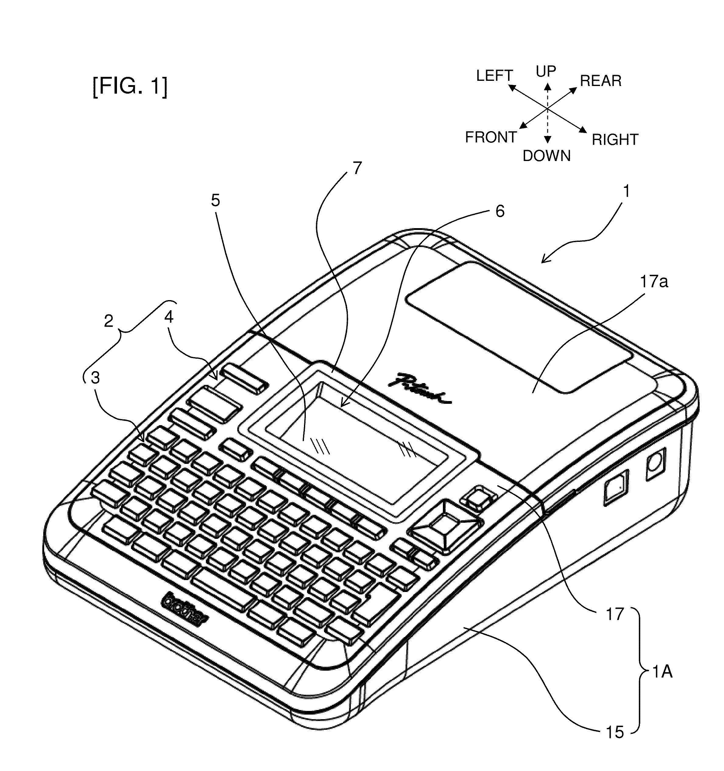
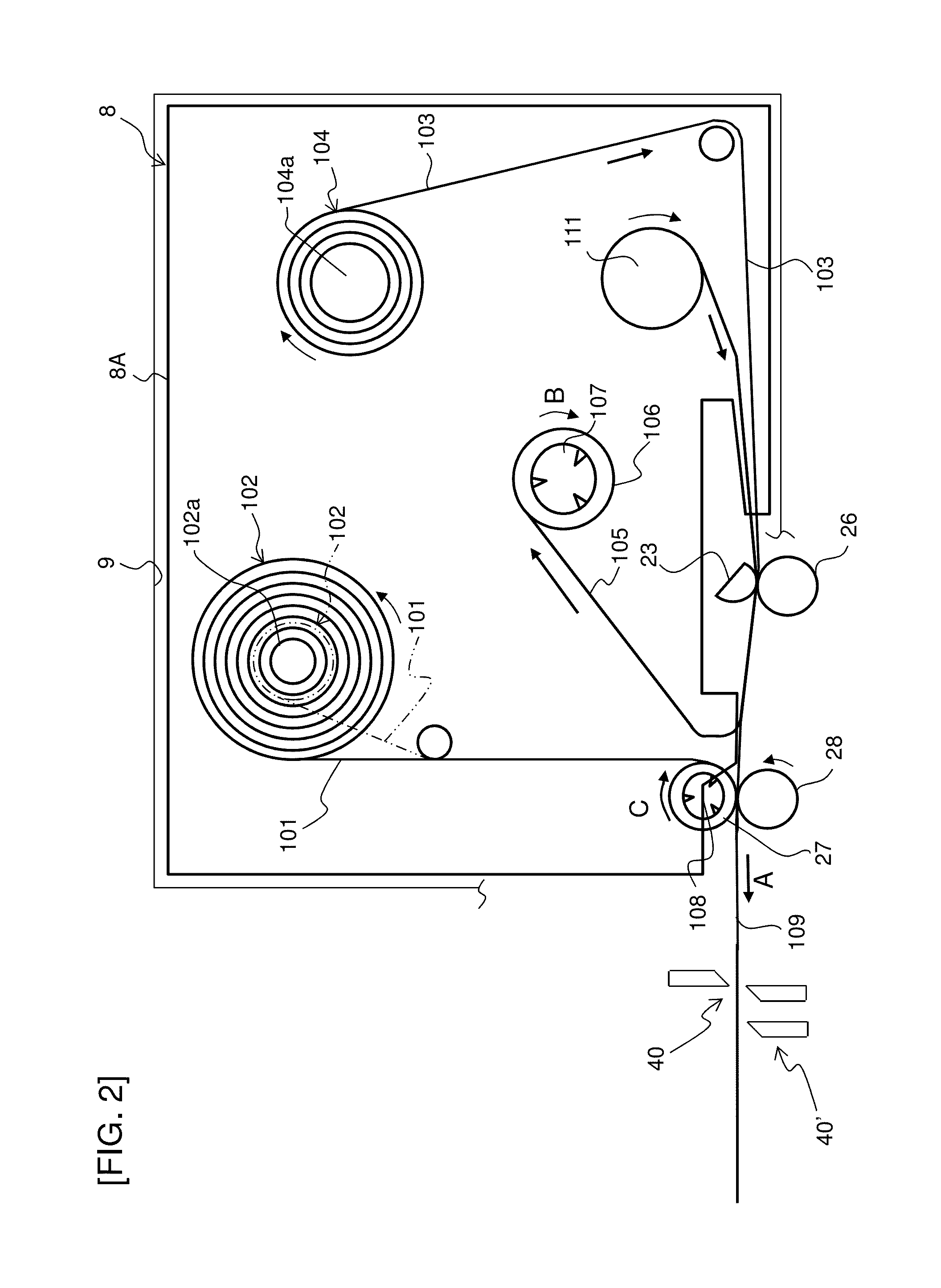
[0028]As shown in FIG. 1, a print label producing apparatus 1 of this embodiment comprises a housing 1A constituting an outer frame. The housing 1A comprises a resin lower cover 15 constituting an apparatus lower surface and an apparatus side surface, and a resin upper cover 17 constituting an apparatus upper surface. The upper cover 17 comprises a cartridge cover 17a that covers a cartridge holder 9 (refer to FIG. 2 described later) on a rear portion side, and the cartridge cover 17a is capable of opening and closing with the rear end portion serving as the fulcrum point. An opening 6 of a rectangular opening shape, for example, adjacent to the cartridge cover 17a and a transparent panel 7 mounted so as to block this opening 6 are disposed on the front portion side of the upper cover 17, and a display portion ...


PUM


Abstract

The disclosure discloses a printer comprising a printing-head, a cutter, a print object receiving portion, an increment mode receiving portion, a cutting mode receiving portion, and a printing control portion. The printer continually produces a plurality of printed matter wherein the print object is respectively formed in a predetermined order. The print object receiving portion receives an input operation for the print object which is disposed in at least one block that includes a print identifier that can be incremented. The increment mode receiving portion receives a setup operation for an increment mode. The cutting mode receiving portion receives a setup operation for a cutting mode at a boundary. The printing control portion controls the feeder and the printing-head to generate a plurality of the printed matter in which is respectively formed the print object which includes the print identifier incremented, and which is cut using the cutting mode.

Description

CROSS-REFERENCE TO RELATED APPLICATION[0001]The present application claims priority from Japanese Patent Application No. 2013-118767, which was filed on Jun. 5, 2013, the disclosure of which is incorporated herein by reference in its entirety.BACKGROUND[0002]1. Field[0003]The present disclosure relates to a printer and printing method that continually produces a plurality of printed matter, each comprising a print object.[0004]2. Description of the Related Art[0005]In the past, there have been known printers that continually produce a plurality of printed matter, each comprising a print object. According to such a printer (tape printing apparatus), print formation of the print object (characters and symbols) is performed by printing means (a thermal head) on a print-receiving tape (laminated film tape) fed by feeding means (connecting rollers), thereby continually producing a plurality of printed matter (labels), each comprising the print object. The print object includes a print id...

Claims


Application Information

Patent Timeline
IPC IPC(8): B41J11/66
CPCB41J11/663B41J11/703
Inventor TOMOMATSU, YOSHITSUGUKAWAI, JUNYAISHII, HIDEKAZU
Owner BROTHER KOGYO KK
Learn More