Printer and printing system

a printing system and printing technology, applied in the field of printing system, can solve the problems of burdensome operation for operators, inability to distinguish between bootable and unbootable target devices based on outward appearance, and inability to fully understand office automation equipment. the effect of improving the convenience of operators

Inactive Publication Date: 2010-12-09
BROTHER KOGYO KK
View PDF17 Cites 6 Cited by
  • Summary
  • Abstract
  • Description
  • Claims
  • Application Information

AI Technical Summary

Benefits of technology

[0018]The second aspect of the present disclosure for achieving the above-described objects is a printing system that is connected to a printer and target device in a manner that enables information transmission and reception by wired or wireless communication, wherein the printer performs information transmission and reception with the target device by host communication device, thereby functioning as a host-side device of the target device. In the printer, when the host communication device transmits and receives information with the target device, the target processing portion performs predetermined processing in accordance with the information on the target device side acquired by the target device side. With this arrangement, the printer which serves as a host-side device determines the connectability with the target device, notifies the operator in accordance with the determination result and, in a case where the target device is another printer that differs from the host, acquires the printing related information of the other printer, thereby making it possible to execute printing using the appropriate printer in accordance with the print form intended by the operator. Thus, operator convenience is improved.

Problems solved by technology

Such operations have been burdensome to the operator, especially those without a thorough understanding of office automation equipment, such as the elderly and children.
Since it is difficult to provide interfaces corresponding to all models of each target device, however, there are inevitably bootable models for which a corresponding interface has been provided, and unbootable models for which a corresponding interface has not been provided.
Nevertheless, the operator is unable to distinguish between the bootable and unbootable target devices based on outward appearances.
For this reason, the operator must suffer the extreme inconvenience of connecting each arbitrary target device to the printer using a USB cable or the like, and testing each device one by one to see if the device is bootable.
However, to construct a fixed system with such extensive network connections is extremely cumbersome for the operator.
Additionally, the network connections may result in recognition errors or communication errors as a result of the effects of the communication environment or the like, and prompt recovery from such errors is not easy for an operator having a normal skill level.
Further, depending on the environment, network construction itself may be difficult and, in such a case, the above-described prior art does not particularly take that into consideration.
Thus, as described above, each of the aforementioned prior arts increases the labor burden of the operator, decreasing operator convenience.

Method used


Image

  • Printer and printing system
  • Printer and printing system
  • Printer and printing system

Examples


embodiment 1

[0052]The following describes embodiment 1 of the present disclosure with reference to accompanying drawings.

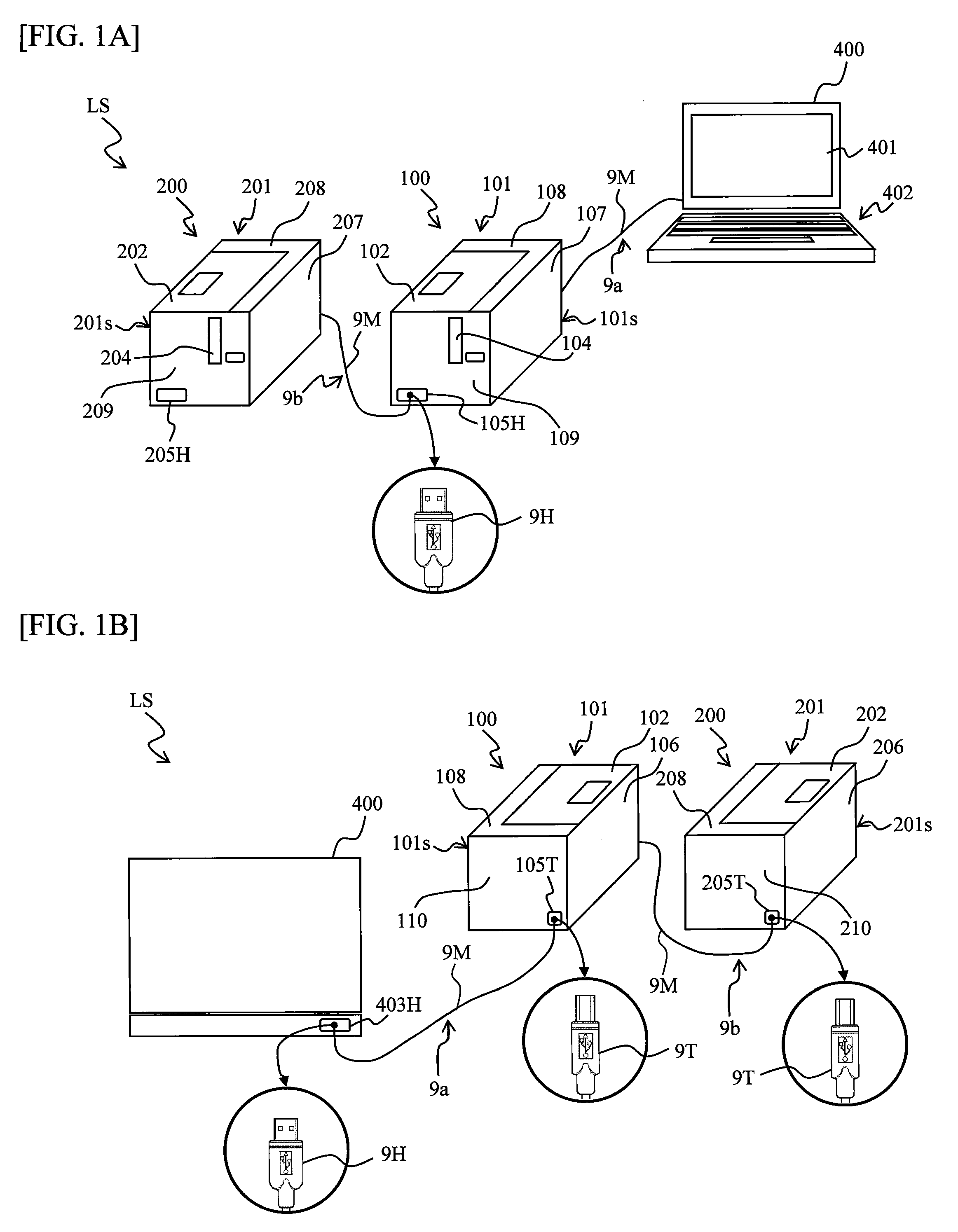
[0053]The configuration of the label producing system of this embodiment will now be described with reference to FIG. 1.

[0054]In FIG. 1A and FIG. 1B, a label producing system LS comprises a label producing apparatus 100 and a label producing apparatus 200 capable of producing a print label L (refer to FIG. 5 described later) on which desired printing was performed, an operation terminal 400 for operating the above-described label producing apparatus 100, and a plurality of communication cables 9 (in this example, two communication cables 9a and 9b) comprising a USB cable, in this example.

[0055]The label producing apparatus 100 comprises an apparatus main body 101, and a housing 101s of an overall rectangular shape as an outer shell comprising an upper surface part 108, a lower surface part (not shown), a front surface part 109, a rear surface part 110, and both left and right...

second embodiment

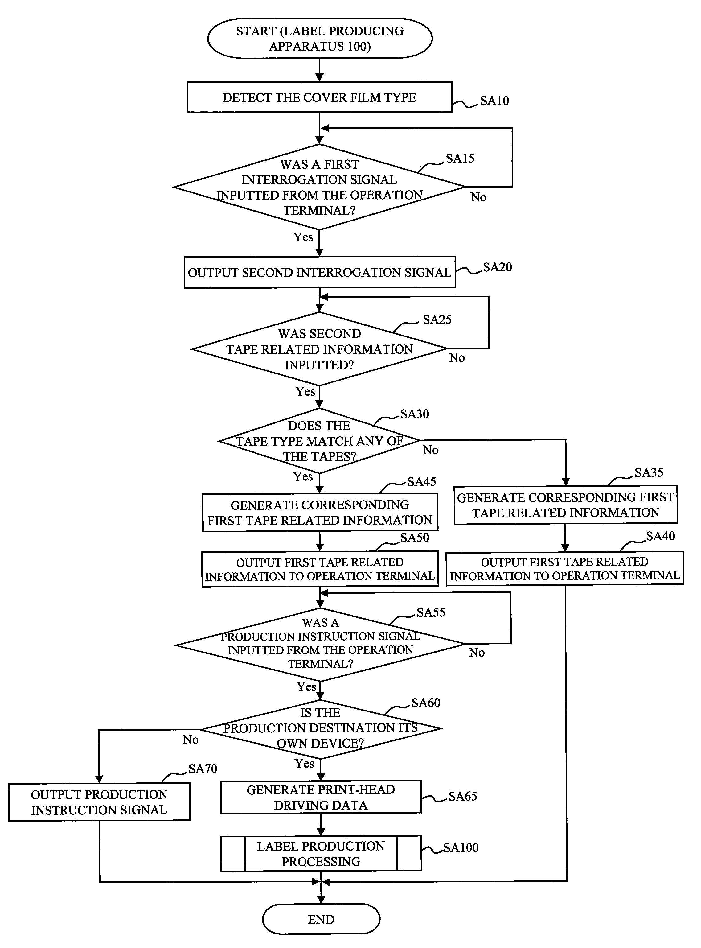
[0305]The following describes the present disclosure with reference to accompanying drawings. In this embodiment, the above-described label producing apparatus 100 has a function that determines whether or not the connection to the connected target device is suitable when the label producing apparatus 100 is used as a printer with a USB host function.

[0306]The system configuration of a print label producing system LS″ that includes the label producing apparatus 100 according to this embodiment will now be described with reference to FIG. 21.

[0307]In FIG. 1, the print label producing apparatus LS″ comprises the label producing apparatus 100 connected to the first connector 9H (described later) of the above-described communication cable 9 (hereinafter referred to as USB cable 9) comprising a USB cable, and a target device 500 (a barcode reader in this example; hereinafter suitably referred to as “barcode reader 500”) connectable to the second connector 9T (described later) of the abov...


PUM


Abstract

This disclosure discloses a printer comprising: a host communication device that performs information transmission and reception by wired or wireless communication for the functioning as a host device of a target device; and a target processing portion that performs predetermined processing in accordance with target device information acquired from said target device when said host communication device performs information transmission and reception with said target device.

Description

CROSS-REFERENCE TO RELATED APPLICATIONS[0001]This application claims priority from Japanese Patent Application No. 2009-133586, which was filed on Jun. 3, 2009, No. 2009-137507, which was filed on Jun. 8, 2009, and No. 2009-182039, which was filed on Aug. 5, 2009, the disclosure of which are incorporated herein by reference in its entirety.BACKGROUND[0002]1. Field[0003]The present disclosure relates to a printer and printing system connectable to a variety of target devices.[0004]2. Description of the Related Art[0005]In the past, a printer was connected to a host device, such as a PC, and printing was performed based on the control information from the host device. As a result, when an operator wanted to use the printer, the operator needed to connect the PC and printer using a cable or the like, and suitably operate the PC keyboard, mouse, or other device to set up various print settings and provide print execution instructions. Such operations have been burdensome to the operator...

Claims


Application Information

Patent Timeline
Patent Type & Authority Applications(United States)
IPC IPC(8): G06K15/02G06F3/12G06F13/42G06F3/00G06F1/26
CPCG06F3/1204G06F3/1294G06F3/1285G06K15/4045G06F3/1226G06K15/007
Inventor YASUI, JUNICHIMIWA, TAKAHIROSUZUKI, YUICHIRO
Owner BROTHER KOGYO KK
Why Eureka
Try Eureka