Tag label editing apparatus and tag label producing apparatus

a label and label technology, applied in the direction of digitally marking record carriers, digital output to print units, instruments, etc., can solve the problems of reducing the visual quality of print, bumps and indentations on the label surface, and printing defects such as thin spots, so as to improve operator convenience

Inactive Publication Date: 2008-10-30
BROTHER KOGYO KK
View PDF0 Cites 7 Cited by
  • Summary
  • Abstract
  • Description
  • Claims
  • Application Information

AI Technical Summary

Benefits of technology

[0016]As described above, display of the print image of the tag label and the disposed position of the RFID circuit element during editing makes it easy for the operator to visually understand the positional relationship of the print area and the RFID circuit element area of the tag label to be produced. Thus, the present disclosure makes it possible for the operator to adjust the positional relationship of these two areas to a desired form according to personal preference and intent, thereby improving operator convenience.

Problems solved by technology

Here, in the RFID label produced by the tag label producing apparatus, a difference sometimes occurs between the label thickness at the disposed area of the RFID circuit element To and the label thickness at other areas, resulting in the formation of bumps and indentations on the label surface.
As a result, in a case where printing is performed at the disposed area of the RFID circuit element To, the possibility exists that the bumps and indentations will decrease the visual quality of the print.
Also, in a case where the tag label is produced by directly printing on thermal tape comprising a built-in RFID circuit element To, for example, rather than by printing on print-receiving tape and bonding that tape to the tag tape as described above, the bumps and indentations on the tape surface caused by the thickness of the RFID circuit element To may cause printing defects such as thin spots.
Nevertheless, in the tag label editing apparatus of prior art, only the print image is displayed on the display device, not the position of the RFID circuit element To.

Method used


Image

  • Tag label editing apparatus and tag label producing apparatus
  • Tag label editing apparatus and tag label producing apparatus
  • Tag label editing apparatus and tag label producing apparatus

Examples


embodiment 1

[0099]The following describes embodiment 1 of the present disclosure with reference to accompanying drawings.

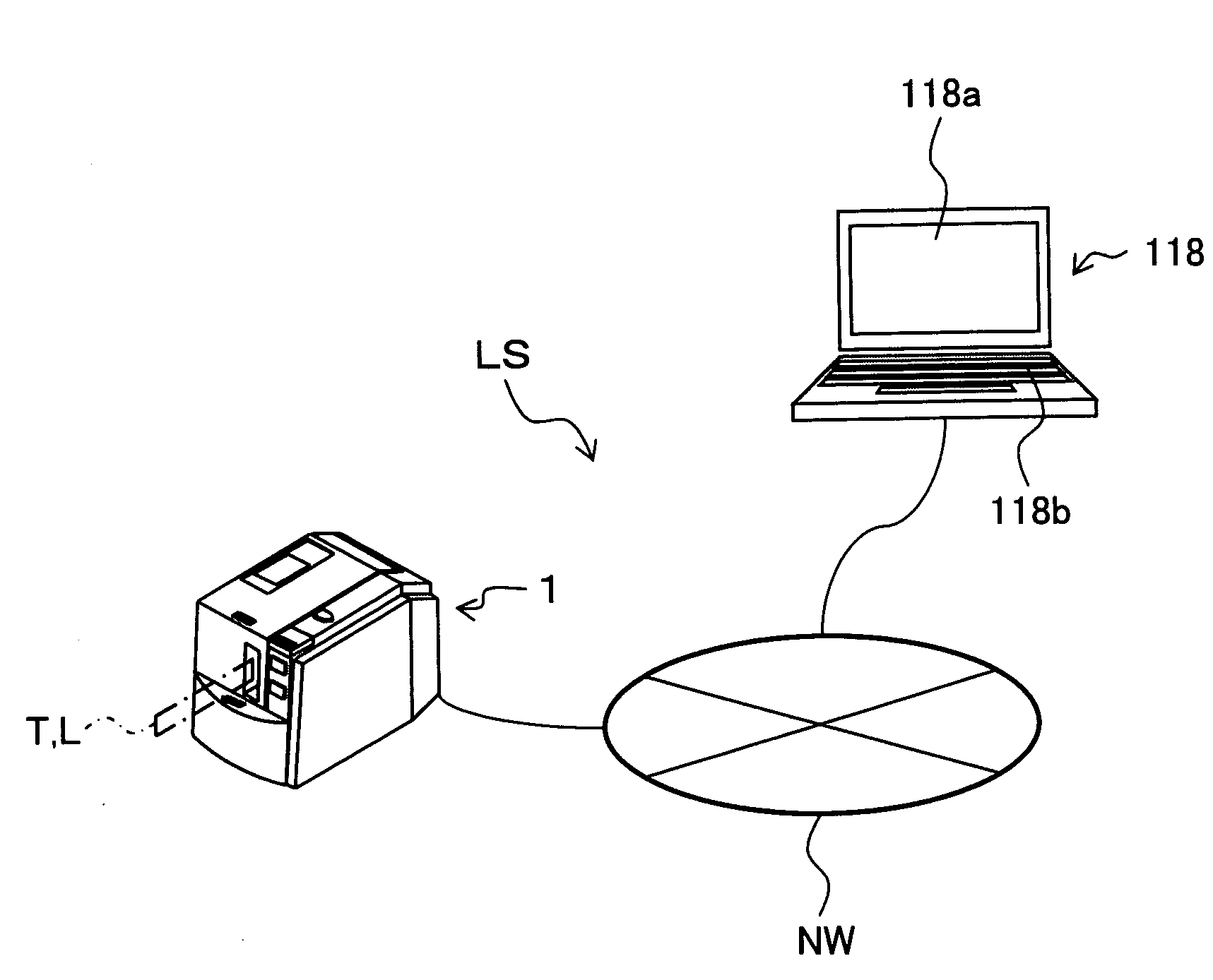
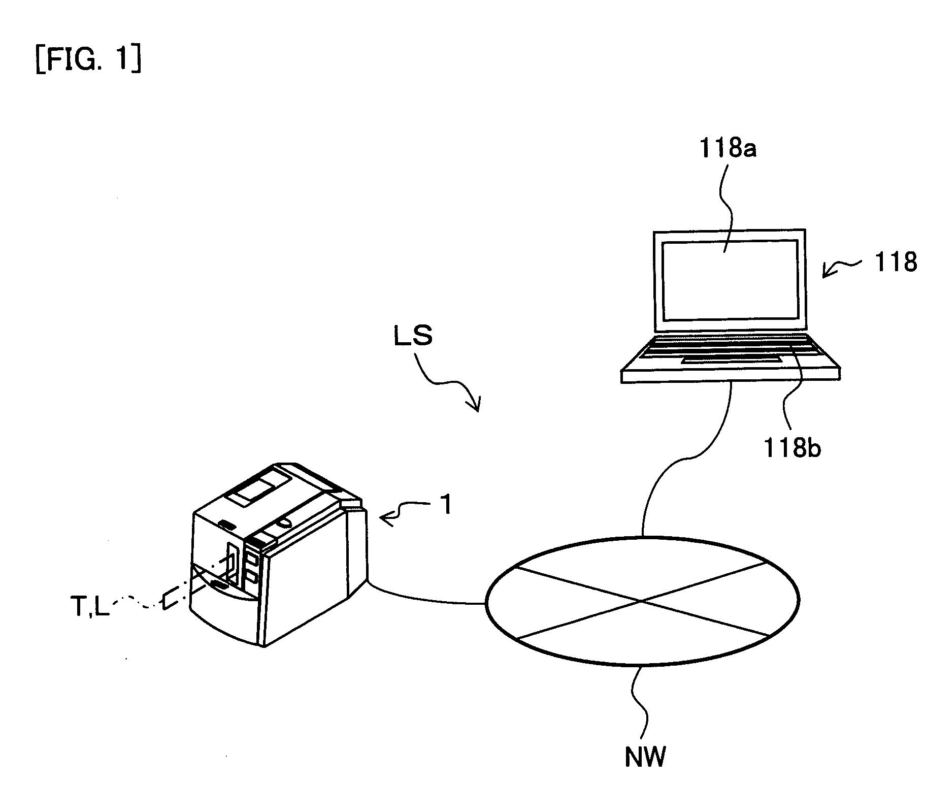
[0100]In the label manufacturing system LS shown in FIG. 1, a label producing apparatus 1 of the present embodiment is connected to a PC 118 via a wired or wireless communication line NW. The PC 118 comprises a display part 118a such as a liquid crystal display, and an operation part 118b such as a keyboard and mouse, making it possible to edit the print content when producing a label (i.e., a label with print; that is, an RFID label T or regular label L) using the label producing apparatus 1.

embodiment 6

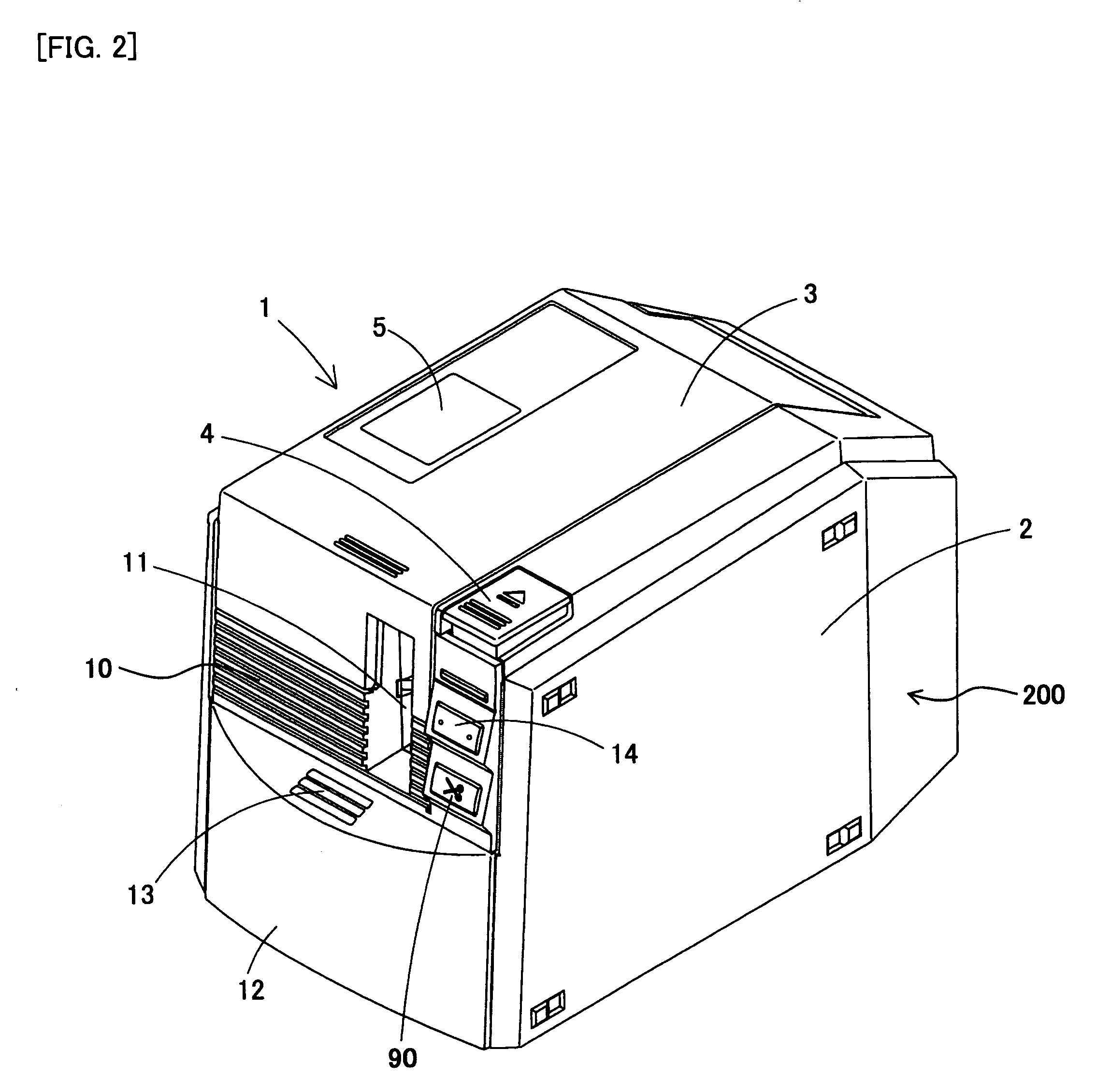
[0101]The label producing apparatus 1, as shown in FIG. 2, produces an RFID label T with print using a base tape comprising an RFID circuit element To (hereinafter, suitably referred to as “RFID circuit element To for label production”) in the apparatus, produces a regular label L using an regular base tape not comprising an RFID circuit element To, and reads (acquires) information from the RFID circuit element To (hereinafter suitably referred to as “RFID circuit element To for information acquisition”) from outside the apparatus, based on the operation from the 118. The RFID information read function from outside this apparatus will be described in detail in embodiment 6 described later.

[0102]The label producing apparatus 1 comprises an apparatus main body 2 having a housing 200 of a substantially six-sided (substantially cubical) shape, and an opening / closing lid 3 provided on the upper surface of the apparatus main body 2 so as to freely open and close (or detach).

[0103]The hous...

embodiment 2

[0282]The following describes embodiment 2 of the present disclosure with reference to accompanying drawings.

[0283]The configurations of the label manufacturing system LS of the present embodiment and the PC 118 and label producing apparatus 1 thereof are the same as those of the above embodiment 1, and detailed descriptions thereof will be omitted.

[0284]The content shown in FIG. 29 is executed by a control circuit 130A (not shown) of the PC 118 when the RFID label T is produced using the label manufacturing system LS of the present embodiment. Note that the control circuit 130A starts this flow when, for example, the operator enters a suitable operation that instructs the system to start tag label editing.

[0285]In FIG. 29, Step S510 to step S520 are the same as step S10 to step S20 of the aforementioned FIG. 8. In these steps, the decision is made as to whether or not the cartridge information detected by the cartridge sensor 81 of the label producing apparatus 1 and acquired by th...


PUM


Abstract

A PC capable of editing the print content to be printed by a print head on a cover film to which a base tape in which an RFID circuit element comprising an IC circuit part that stores information and a loop antenna that transmits and receive information is affixed, the PC comprising a display part that determines a printable area of the print head on the cover film and to display a print image to be printed by the print head on the RFID label to be produced and a disposed area of the RFID circuit element in the RFID label to be produced.

Description

CROSS-REFERENCE TO RELATED APPLICATIONS[0001]This application claims priority from JP 2007-118852, filed Apr. 27, 2007, the contents of which are hereby incorporated by reference.BACKGROUND[0002]1. Field[0003]The present disclosure relates to a tag label editing apparatus capable of editing print content when a tag label having an RFID circuit element comprising an IC circuit part configured to store information and a tag antenna configured to transmit and receive information is produced, and a tag label producing apparatus for producing tag labels.[0004]2. Description of the Related Art[0005]An RFID (Radio Frequency Identification) system, for example, that performs reading / writing between a small-sized RFID tag and a reader / writer (reading / writing apparatus) in a non-contact manner is known. For example, an RFID circuit element provided to a label-shaped RFID tag (RFID label) comprises an IC circuit part configured to store predetermined RFID tag information, and an antenna config...

Claims


Application Information

Patent Timeline
Patent Type & Authority Applications(United States)
IPC IPC(8): G06K1/00
CPCG06F17/212G06F17/30017G06F16/40G06F40/106
Inventor SUZUKI, MIKITOSHIMORIYAMA, SATORUIKEDO, TATSUHIROOSUKA, NORIYUKIYAMAGUCHI, KOSHIRO
Owner BROTHER KOGYO KK
Why Eureka
Try Eureka