Screw-in heat exchanging element for water heaters

a technology of heat exchange element and water heater, which is applied in the field of screw-in heat exchange element for water heater, can solve the problems of increasing the cost of control system and pump, and increasing the cost of water heating

Inactive Publication Date: 2014-12-11
COMPTON JOHN JOSEPH
View PDF18 Cites 6 Cited by
  • Summary
  • Abstract
  • Description
  • Claims
  • Application Information

AI Technical Summary

Benefits of technology

The patent text describes an improvement for water heating systems. Specifically, it describes a screw-in heat exchanging element for water heaters that can be used in a dedicated heating element receptacle of a water tank. The technical effect of this improvement is more efficient and effective water heating in a compact space.

Problems solved by technology

Energy costs also vary depending on the heating method used.
The energy cost of heating water using a standard electrical heating element may be relatively high compared to other means of heating water such as using solar, heat pump, or gas-fired technologies.
Although active systems provide better control than other systems, control systems and pumps may be expensive and require additional energy to operate.
Many previously mentioned water heating systems are either relatively expensive or require extensive installation procedures which drive up the cost of the systems to surpass the real or perceived benefit gained from implementing such systems.
In their current configuration, existing water heating systems may lack consumer buy-in without a dramatic reduction in cost or ease of installation.

Method used


Image

  • Screw-in heat exchanging element for water heaters
  • Screw-in heat exchanging element for water heaters
  • Screw-in heat exchanging element for water heaters

Examples


Embodiment Construction

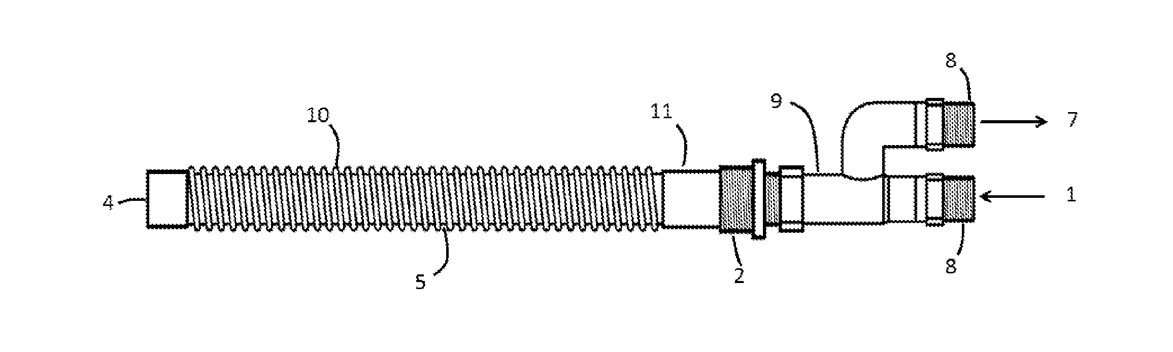
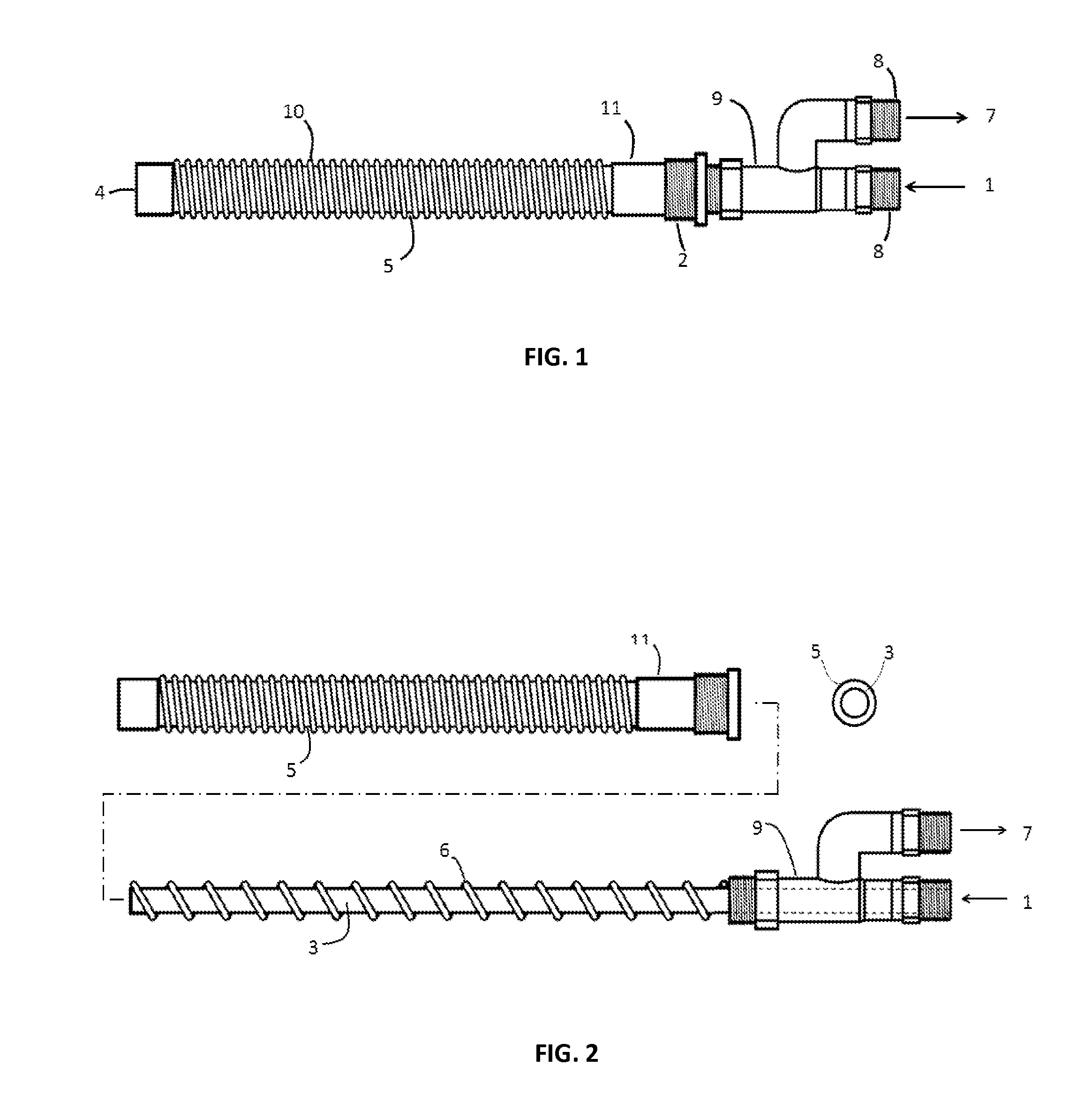
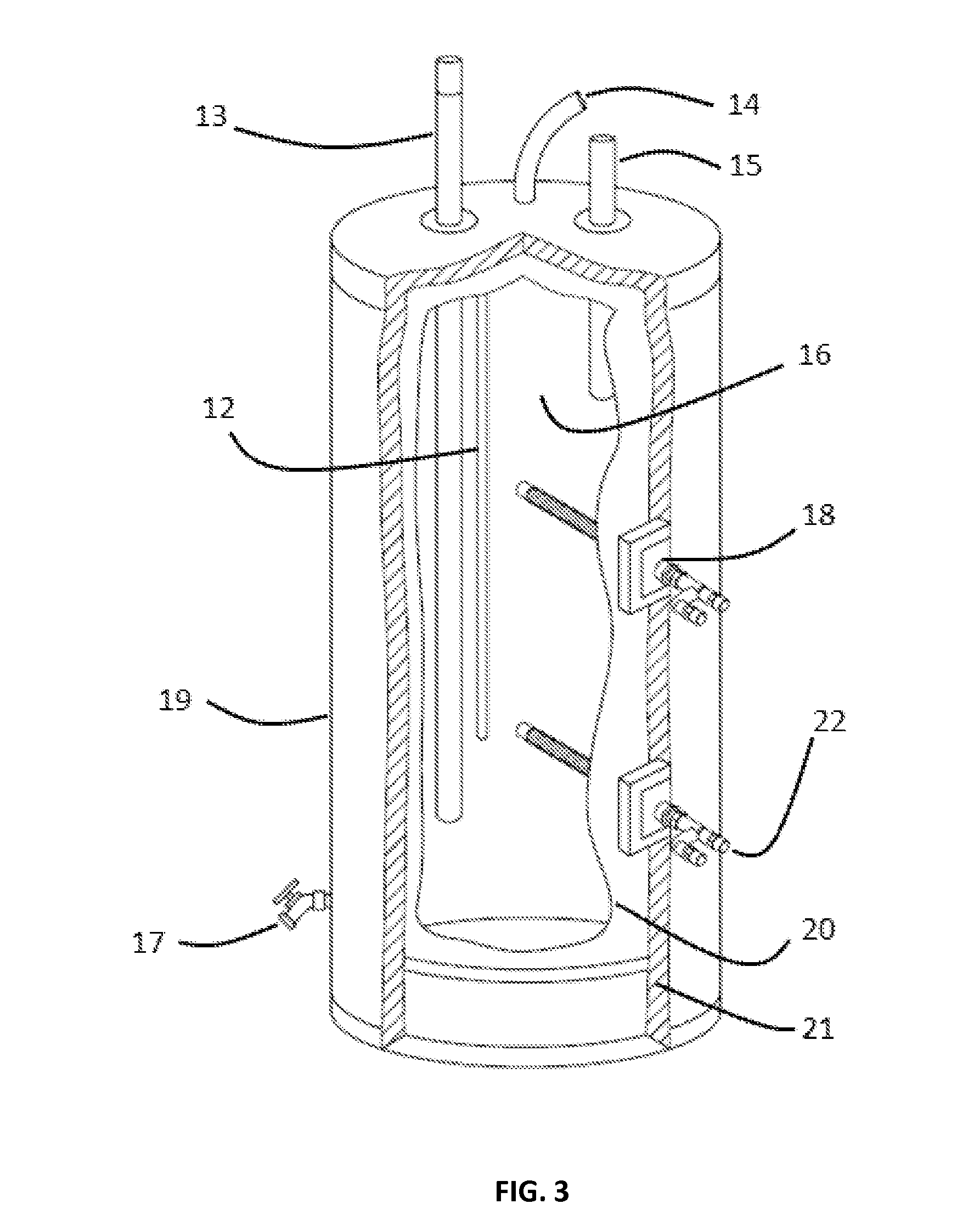
[0024]This document features a screw-in heat exchanging element for water heaters designed to take the place of one or more standard electric heating elements found on water heating tanks. There are many features of screw-in heat exchanging element for water heaters implementations disclosed herein, of which one, a plurality, or all features or steps may be used in any particular implementation.

[0025]In the following description, reference is made to the accompanying pictures which form a part hereof, and which show by way of illustration possible implementations. It is to be understood that other implementations may be utilized, and structural, as well as procedural, changes may be made without departing from the scope of this document. As a matter of convenience, various components will be described using exemplary materials, sizes, shapes, dimensions, and the like. However, this document is not limited to the stated examples and other configurations are possible and within the te...


PUM


Abstract

A screw-in heat exchanger which is adapted to a dedicated heating element receptacle, commonly found on domestic electric hot water heater tanks, which allows a tank's water to be heated or cooled while circulating a hot or cold heat transfer fluid through the heat exchanger.

Description

CROSS-REFERENCE TO RELATED APPLICATIONS[0001]This application claims the benefit of provisional patent application Ser. No. 61 / 832,137, filed 2013 Jun. 6 by the present inventor.BACKGROUND[0002]1. Prior Art[0003]The following is a tabulation of some prior art that presently appears relevant:U.S. PatentsPat. No.Kind CodeIssue DatePatentee6,837,303B2Jan. 4, 2005Butler4,865,005Sep. 12, 1989Griffith4,926,830May 22, 1990McNelley1,849,175AMar. 15, 1932GrantU.S. Patent Application PublicationsPublication Nr.Kind CodePubl. DateApplicant2003 / 0159804A1Jan. 4, 2005Butler[0004]2. Background of Invention[0005]Potable domestic water may be heated various ways. Energy costs also vary depending on the heating method used. The energy cost of heating water using a standard electrical heating element may be relatively high compared to other means of heating water such as using solar, heat pump, or gas-fired technologies. Solar water heating may be viewed as a cost effective method by collecting the su...

Claims


Application Information

Patent Timeline
Patent Type & Authority Applications(United States)
IPC IPC(8): F28F9/007F24H1/00
CPCF24H1/0018F28F9/007F24H1/20F24H9/1809F24D2220/06F28F2275/20F28F2210/06F28F9/0246F28D7/12F28D20/0034F28F1/36F28D2020/0078F24H9/1818
Inventor COMPTON, JOHN JOSEPH
Owner COMPTON JOHN JOSEPH
Why Eureka
Try Eureka