Image processing apparatus and control method thereof

Inactive Publication Date: 2014-12-18
CANON KK
View PDF5 Cites 10 Cited by
  • Summary
  • Abstract
  • Description
  • Claims
  • Application Information

AI Technical Summary

Benefits of technology

The present invention aims to solve the problem of decreased object detection processing speed while performing object detection on both out-camera and in-camera images without increasing cost or power consumption. The invention proposes an object detection technique that can suppress the decrease in detection processing rate.

Problems solved by technology

If an object detection unit is added to separately process the out-camera image and the in-camera image and suppress a decrease in the frame rate, the cost and power consumption increase.

Method used


Image

  • Image processing apparatus and control method thereof
  • Image processing apparatus and control method thereof
  • Image processing apparatus and control method thereof

Examples


second embodiment

[0068]An example will be described next as the second embodiment with reference to FIGS. 4A to 6, in which an in-camera image 135 is laid out in an area (to be referred to as a free area hereinafter) where the image is not superimposed on persons included in an out-camera image 125, and composed.

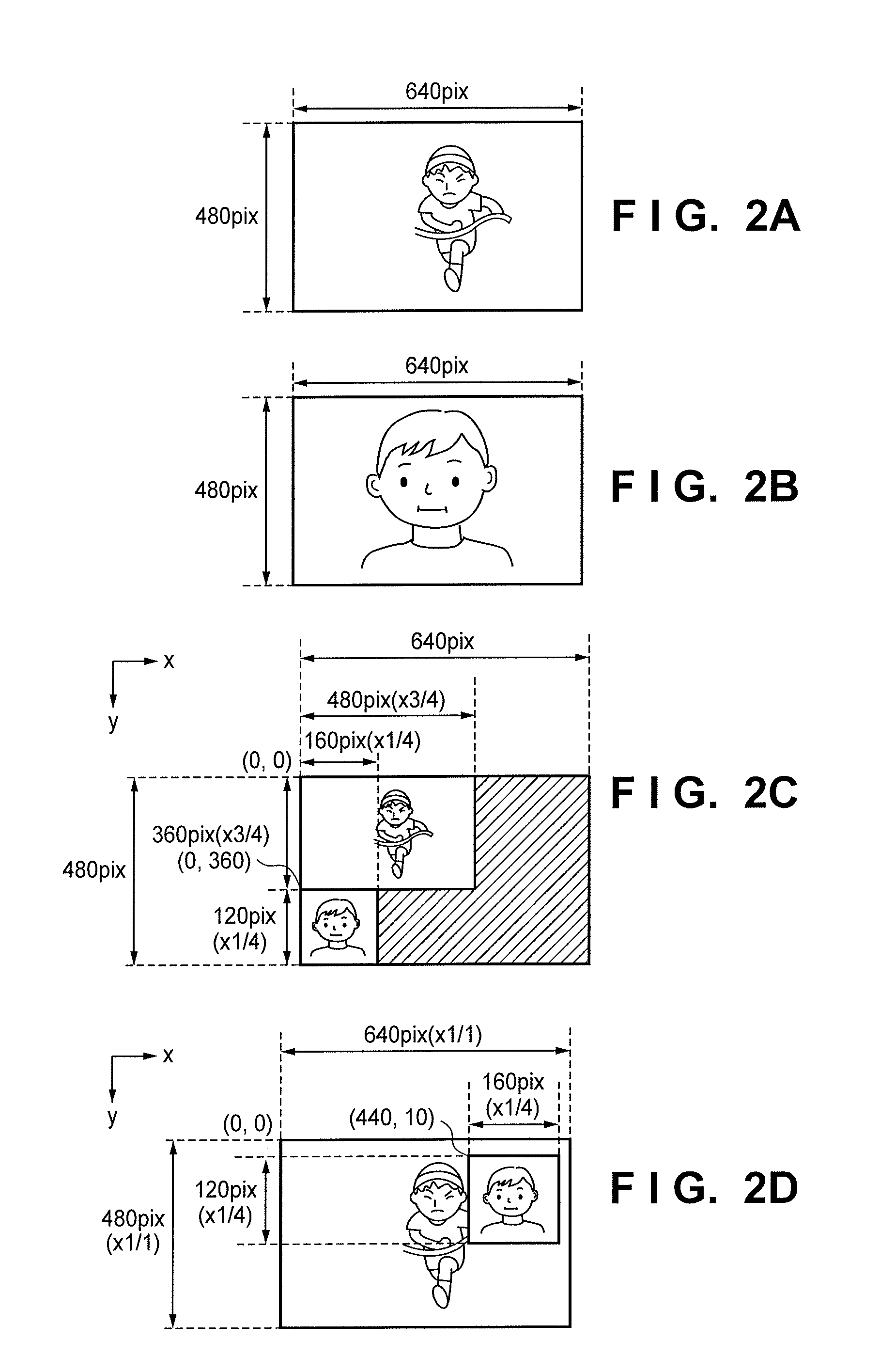
[0069]FIG. 4A shows an example of the out-camera image 125 that is the same as in FIG. 2A, and its size is 640×480. FIG. 4B shows an example of the in-camera image 135 that is the same as in FIG. 2B, and its size is 640×480. FIG. 4C shows an example of a face detection image 191, in which the area of the out-camera image 125 is divided into a plurality of areas (16 areas in FIG. 4C), and the in-camera image 135 is resized so as to fall within a divided area and laid out. Referring to FIG. 4C, reference numeral 400 denotes the face detection image 191 of this embodiment, whose size is a size (640×480) inputtable to a face detection unit 160 and is equal to the size of the out-camera image 125...


PUM


Abstract

An image processing apparatus comprises a first composition processing unit configured to compose a first image generated by a first image capturing unit and a second image generated by a second image capturing unit and generate a third image; and a detection unit configured to detect an area of the object from the third image.

Description

BACKGROUND OF THE INVENTION[0001]1. Field of the Invention[0002]The present invention relates to a technique of detecting an object from an image.[0003]2. Description of the Related Art[0004]Recent digital cameras include a camera (in-camera) for shooting a photographer himself / herself or an object on the photographer side in addition to a normal camera (out-camera) for shooting an object seen from the photographer. A digital camera incorporating such out-camera and in-camera can perform shooting by simultaneously releasing the shutters of the out-camera and in-camera upon pressing a shutter button and record an image on the in-camera side in association with an image on the out-camera side.[0005]For example, Japanese Patent Laid-Open No. 2008-107942 describes a technique of alternately detecting the object of an out-camera image and that of an in-camera image, comparing the object of the out-camera image and that of the in-camera image, and determining spoofing when the objects mat...

Claims


Application Information

Patent Timeline
IPC IPC(8): G06T11/60G06K9/00G06T3/40
CPCG06T11/60G06T3/40G06T2207/30201G06K9/00369G06K9/00228G06V40/161H04N23/45H04N23/611G06V40/103
Inventor TAKEUCHI, YUSUKE
Owner CANON KK
Why Eureka
Try Eureka