Heat exchanger testing device

a technology of heat exchanger and testing device, which is applied in the direction of heat exchange simulation, lighting and heating apparatus, instruments, etc., can solve the problems of reducing the heat transfer capacity of the same, corroding or leaking of various portions of the heat exchanger and conduit,

Active Publication Date: 2015-01-01
KNEW VALUE
View PDF31 Cites 13 Cited by
  • Summary
  • Abstract
  • Description
  • Claims
  • Application Information

AI Technical Summary

Benefits of technology

[0006]In one or more embodiments, the present invention provides a process and a device that can be placed inline with, or in a parallel line to, the fluid carrying conduits of the heat exchanger. The device can be subjected to the identical flow rates, temperatures, and other conditions of the heat exchangers that are used in the process (such as tube-and-shell heat exchangers) or other conduits. Accordingly, the testing device will be operated under nearly identical conditions as the heat exchangers in the plant or process. This will allow portions of the testing device to be disassembled and inspected for scale, corrosion and microbiological matter after a period of exposure time.

Problems solved by technology

The nature of the fluids passing through the heat exchangers and conduits, and the temperatures and other conditions present in the heat exchangers and conduits can lead to problems.
For example, various portions of the heat exchangers and conduits may become corroded as a result of the fluid, conditions or both.
The corrosion can lead to leakage or breakage.
The deposits may interfere with the flow of fluid through the heat exchangers and conduits and may also reduce the heat transfer capacity of same.
Both of these problems are undesirable.
Many of these problems cannot be observed until after the heat exchanger has been online for some time.
Furthermore, many of these problems can only be observed by removing and disassembling the heat exchanger and inspecting the conduits contained therein.
The heat exchangers tend to be very large and can be quite costly.
Additionally, removing the heat exchanger may require a process to shut down, which may impact a facility's production and output.

Method used


Image

  • Heat exchanger testing device
  • Heat exchanger testing device
  • Heat exchanger testing device

Examples


Embodiment Construction

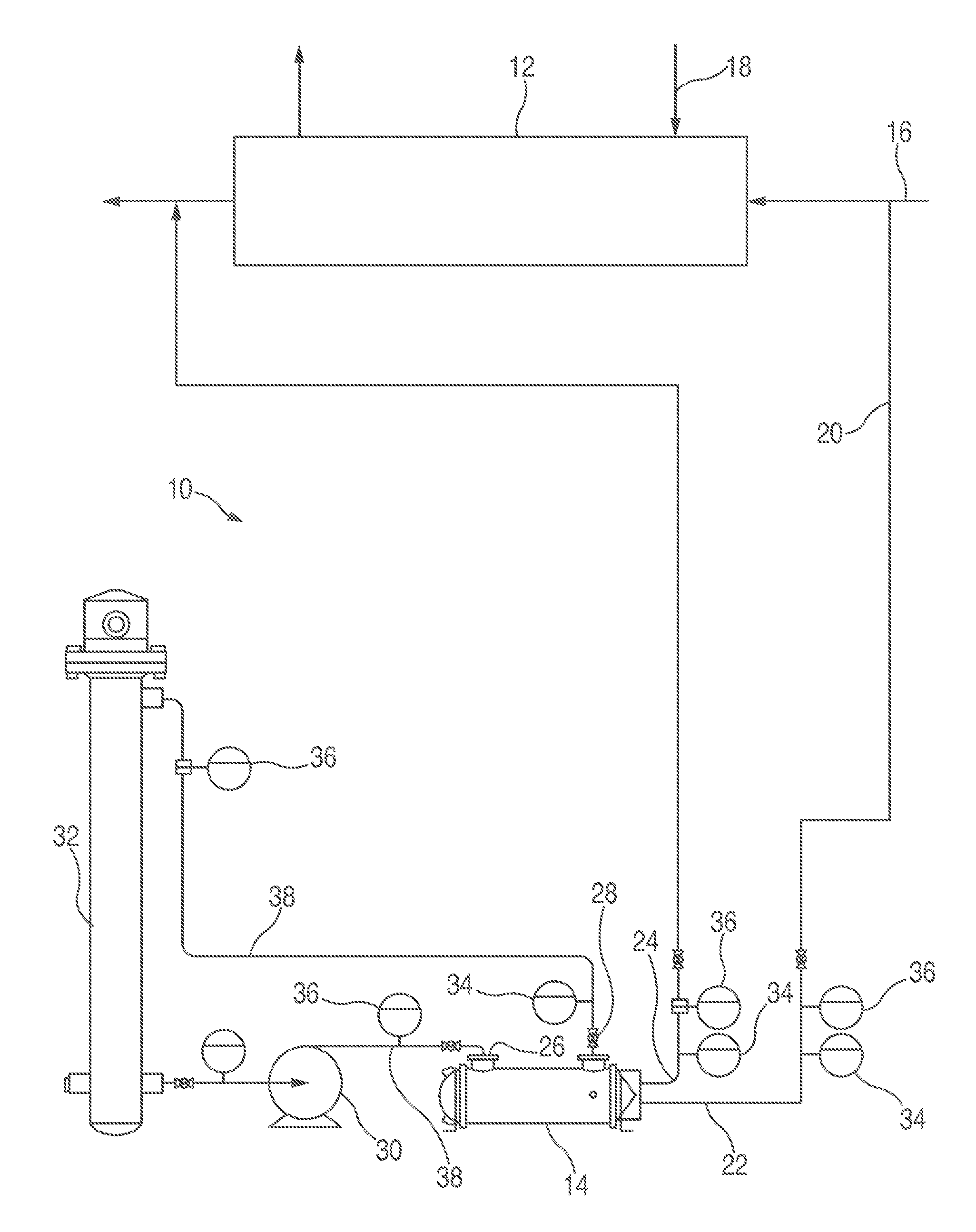
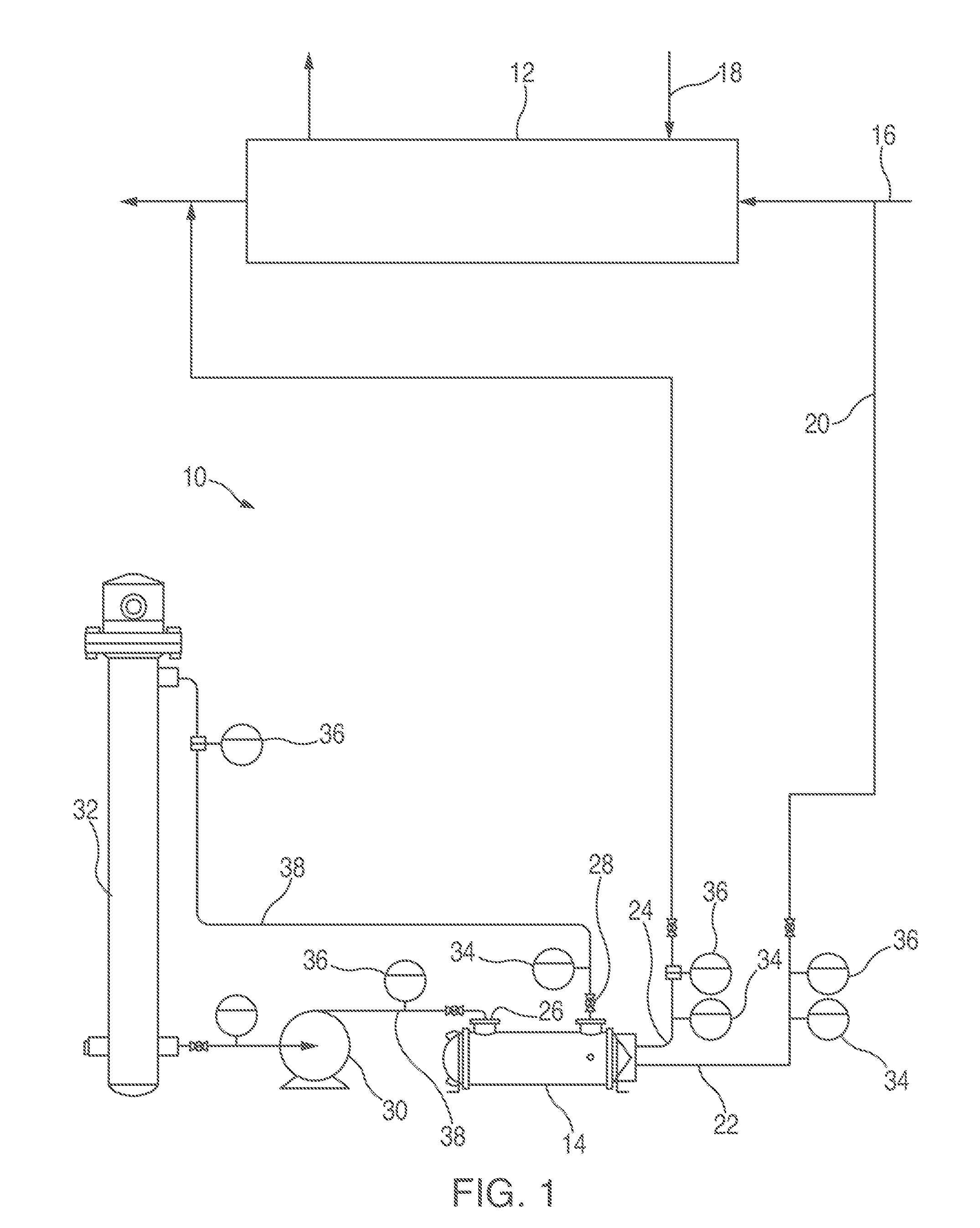
[0029]With reference to FIG. 1, a device 10 according to one or more embodiments of the present invention is shown which include a first heat exchanger 12 and a test heat exchanger 14. The first heat exchanger 12 receives a first fluid, for example via a line 16, and recovers heat from the first fluid, or passes heat to the first fluid, or both. Typically, the first heat exchanger 12 also receives another fluid, for example, via a line 18, which can supply heat to the first fluid or receive heat from the first fluid. These heat exchangers 12 are known.

[0030]In order to test the materials of the first heat exchanger 12, a portion of the first fluid is passed, via a line 20, to the test heat exchanger 14. Accordingly, the test heat exchanger 14 has an inlet 22 for the first fluid and an outlet 24 to return the first fluid to the first heat exchanger 12. The first fluid may be combined with fluid exiting the first heat exchanger 12, and it would still be considered returning the first ...


PUM

PropertyMeasurementUnit
widthaaaaaaaaaa
temperatureaaaaaaaaaa
flow rateaaaaaaaaaa

Abstract

An apparatus and a process for testing fluid from a heat exchanger. A first fluid from a heat exchanger to be tested is passed through a test heat exchanger. A second fluid is circulated through the test heat exchanger with a pump. The second fluid is heated with a heater so that a temperature in the test heat exchanger can be controlled, for example, to so that conditions in the heat exchanger are close to the conditions in the heat exchanger. After a period of time, the test heat exchanger can be removed and inspected, tested, or both. Also, multiple test heat exchangers may be used to test various process conditions. Additionally, the test heat exchangers may include different materials to test various materials.

Description

CROSS-REFERENCES TO RELATED APPLICATIONS[0001]This application claims priority to U.S. Provisional Patent Application No. 61 / 841,643 filed on Jul. 1, 2013, the entirety of which is incorporated herein.BACKGROUND OF THE INVENTION[0002]Heat exchangers often involve fluids flowing through conduits. The nature of the fluids passing through the heat exchangers and conduits, and the temperatures and other conditions present in the heat exchangers and conduits can lead to problems.[0003]For example, various portions of the heat exchangers and conduits may become corroded as a result of the fluid, conditions or both. The corrosion can lead to leakage or breakage. Additionally, the heat exchangers and conduits may develop deposits as a result of materials in the fluid. The deposits may interfere with the flow of fluid through the heat exchangers and conduits and may also reduce the heat transfer capacity of same. Both of these problems are undesirable.[0004]Many of these problems cannot be o...

Claims


Application Information

Patent Timeline
Patent Type & Authority Applications(United States)
IPC IPC(8): G01M99/00G01N25/72
CPCG01M99/005F28F2200/00G01N25/72G01M99/002G01M99/008F28D7/06
Inventor ASPINALL, LAURIN, JOSEPH
Owner KNEW VALUE
Why Eureka
Try Eureka