Electronic cigarette

a technology of electronic cigarettes and cigarettes, applied in the field of electronic cigarettes, can solve the problems of low production efficiency, unfavorable automatic production, complicated assembly,

Inactive Publication Date: 2015-01-29
HUIZHOU KIMREE TECH
View PDF4 Cites 62 Cited by
  • Summary
  • Abstract
  • Description
  • Claims
  • Application Information

AI Technical Summary

Benefits of technology

[0004]The object of the present invention is to provide an electronic cigarette which can prevent the atomizer thereof from being used repeatedl...

Problems solved by technology

Thus, the production efficiency is low, the assembly is complicated, and it is not conducive to automatic production.
Furthermore, because the atomizer and the battery rod can be repeatedly connected with each other for many times, it is difficult to distinguish a us...

Method used


Image

  • Electronic cigarette
  • Electronic cigarette
  • Electronic cigarette

Examples


embodiment 1

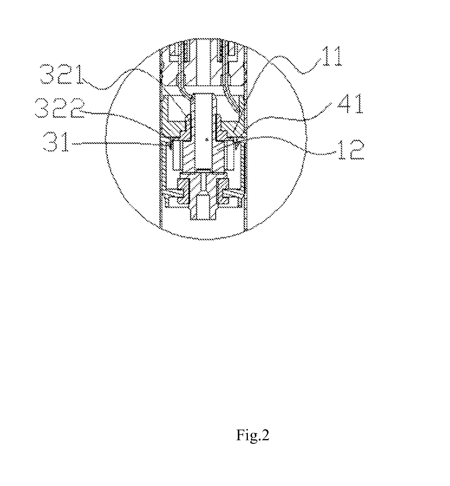
[0047]Referring to FIG. 3, FIG. 4, and FIG. 5, the fixing part 321 is ring-shaped, the first connecting member 3 includes an outer electrode 11 and an inner electrode 12 coaxially sleeved inside the outer electrode 11, and the fixing part 321 is clamped between the inner electrode 12 and the outer electrode 11. The atomizer 1 includes an atomization sleeve, and the outer electrode 11 is inserted in the atomization sleeve to form an interference fit, so that the first connecting member 3 is fixed in the atomizer 1. The buckle body further has an insulating effect between the inner electrode 12 and the outer electrode 11. In order to fit the shape of the outer electrode 11, the fixing part 321 is stepped-shaft-shaped.

embodiment 2

[0048]Referring to FIG. 8, FIG. 9, and FIG. 10, the fixing part 321 is ring-shaped, the first connecting member 3 is provided with an outer electrode 11, an annular groove 113 is defined around a circumference of the outer electrode 11, and the fixing part 321 is embedded in the annular groove 113. As same as the first embodiment, the atomizer 1 includes an atomization sleeve; the outer electrode 11 is inserted in the atomization sleeve to form a interference fit, so that the first connecting member 3 is fixed in the atomizer 1; and the first connecting member 3 further includes an inner electrode 12 coaxially sleeved inside the outer electrode 11. However, a difference between the first embodiment and the second embodiment is that: in the second embodiment, an insulating member is arranged between the outer electrode 11 and the inner electrode 12, and the buckle body does not have the insulating effect between the inner electrode 12 and the outer electrode 11.

embodiment 3

[0049]Referring to FIG. 13, FIG. 14, and FIG. 15, the fixing part 321 is block-shaped, the first connecting member 3 is provided with an outer electrode 11, an exterior of the outer electrode 11 defines a first groove 111 fitting the shape of the fixed part 321, and the fixing part 321 is embedded in the first groove 111. In the aforementioned first and second embodiments, a plurality of snaps 31 is mounted on one buckle body. In the third embodiment, the buckle body and the snap 31 form one-to-one correspondence. As sane as the second embodiment, the atomizer 1 includes an atomization sleeve; the outer electrode 11 is inserted in the atomization sleeve to form an interference fit, so that the first connecting member 3 is fixed in the atomizer 1; the first connecting member 3 further includes an inner electrode 12 coaxially sleeved inside the outer electrode 11; and an insulating member is arranged between the outer electrode 11 and the inner electrode 12.

[0050]In the aforementioned...


PUM


Abstract

This present invention relates to the field of an electronic cigarette, comprising an atomizer, a battery rod, and a connecting structure mounted at a butt-jointed position between the atomizer and the battery rod; the connecting structure includes a first connecting member mounted at an end of the atomizer and a second connecting member mounted at an end of the battery rod; a side surface of the first connecting member is provided with at least one snap that is capable of elastically moving inward along a radial direction of the atomizer, the second connecting member defines a butt-jointed slot configured for receiving the first connecting member, and a slot wall corresponding to the butt-jointed slot defines at least one snap-fit portion matching the snap. The electronic cigarette of the invention can prevent the used atomizer from being misused and repeatedly used.

Description

CROSS-REFERENCE TO RELATED APPLICATIONS[0001]This non-provisional application claims priorities under 35 U.S.C. §119(a) on Patent Application No. 201320447830.X filed in P.R. China on Jul. 25, 2013, the entire contents of which are hereby incorporated by reference.FIELD OF THE INVENTION[0002]This present invention relates to the field of electronic cigarettes, and more particularly to an electronic cigarette.BACKGROUND OF THE INVENTION[0003]An electronic cigarette generally comprises an atomizer and a battery rod. In the electronic cigarettes according to the prior art, most connection types between the atomizers and the battery rods are threaded connections. In assembly, a threaded connection needs to rotate many circles to be fixed stably. Thus, the production efficiency is low, the assembly is complicated, and it is not conducive to automatic production. Furthermore, because the atomizer and the battery rod can be repeatedly connected with each other for many times, it is difficu...

Claims


Application Information

Patent Timeline
IPC IPC(8): A24F47/00A24F40/40
CPCA24F47/008A24F40/40
Inventor LIU, QIUMING
Owner HUIZHOU KIMREE TECH
Why Eureka
Try Eureka