Keyboard having tactile feedback

a technology of tactile feedback and keyboard, applied in the field of keys, can solve the problems of user difficulty in knowing, difficulty in applying the structure of traditional mechanical buttons with a larger stroke, and difficulty for users, and achieve the effect of good operation experien

Inactive Publication Date: 2015-02-05
DARFON ELECTRONICS (SUZHOU) CO LTD +1
View PDF2 Cites 9 Cited by
  • Summary
  • Abstract
  • Description
  • Claims
  • Application Information

AI Technical Summary

Benefits of technology

[0010]The keyboard having tactile feedback provided in the embodiments of the invention is capable of providing a tactile feedback equivalent to a mechanical keyswitch or a membrane keyswitch for a thin keyboard with small stroke keyswitches or touch keyswitches. Both light and thin dimension and good operation experience may be provided on the keyboard.

Problems solved by technology

The structure of the traditional mechanical buttons with a larger stroke has been difficult to be applied to such keyboard and therefore most thin keyboards use keyswitches with small stroke or touch button design.
However, whether it is a small stroke keyswitch or a touch keyswitch, it is difficult for a user to sense the feedback when pressing the keyswitch, which makes the user having difficulty knowing whether or not the pressing operation of the keyswitch is completed, which results in some trouble in operation.
However, such type of vibrator is designed to provide only limited monotonous vibration feedback and is incapable of providing a clear sense of the key pressing.

Method used


Image

  • Keyboard having tactile feedback
  • Keyboard having tactile feedback
  • Keyboard having tactile feedback

Examples


first embodiment

The First Embodiment

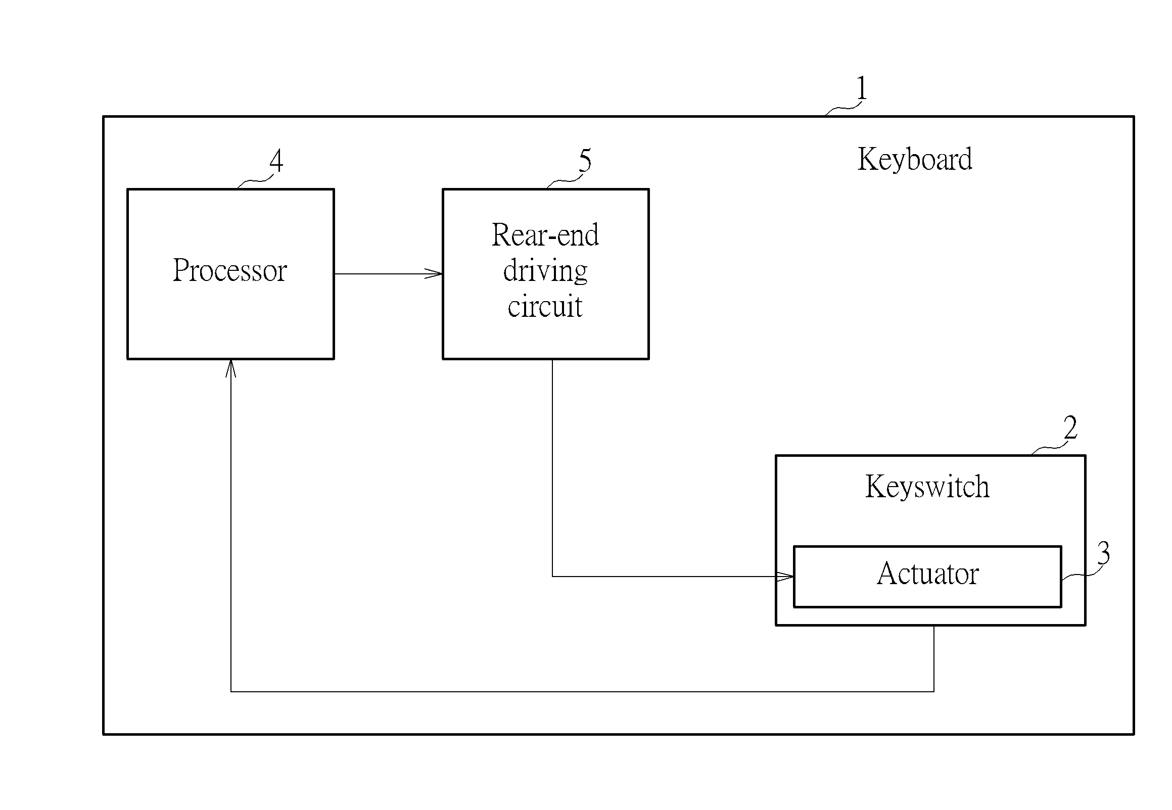
[0030]Please refer to FIG. 4. FIG. 4 is an illustration of waveform of the vibration feedback signal generated according to a first embodiment of the invention. In FIG. 4, the waveform 10 of the first embodiment only contains the acceleration change A measured in Step 150, which means the acceleration change A is directly used as the first type waveform 10 and the vibration feedback signal for driving the actuator 3, C=A. In FIG. 4, the vibration feedback signal C is stored in the processor 4 and can be further divided into a first vibration feedback signal 17 and a second vibration feedback signal 18, i.e., the acceleration change A can be divided into a first acceleration change of the pressing stage and a second acceleration change of a releasing stage. When the user presses the keyswitch 2, in the pressing stage, the processor 4 outputs the first vibration feedback signal 17 to the actuator 3 to generate a press vibration transmitted to the keyswitch 2 when t...

second embodiment

The Second Embodiment

[0033]The internal storage space of the processor 4 may be less consumed via storing in the processor 4 only the first vibration feedback signal 17, including the first interval waveform 11, the second interval waveform 12, and the third interval waveform 13, whereas the second vibration feedback signal 18 in the first embodiment, including the fourth interval waveform 14, the fifth interval waveform 15, and the sixth interval waveform 16, is abandoned and not stored in the processor 4. In such way, when the user presses the keyswitch 2, in the pressing stage, the processor 4 outputs the first vibration feedback signal 17 to the actuator 3 to generate a press vibration transmitted to the keyswitch 2 when the keyswitch 2 is during the course change from the released status to the pressed status. In the releasing stage, the processor 4 outputs the first vibration feedback signal 17 again to the actuator 3 to drive the actuator 3 to generate the press vibration aga...

third embodiment

The Third Embodiment

[0034]Please refer to FIG. 5. FIG. 5 is an illustration of waveform of the vibration feedback signal generated according to a third embodiment of the invention. In FIG. 5, the vibration feedback signal C of the waveform 20 of the third embodiment is generated based on a press model waveform and a release model waveform modulated by the periodic signal H, or the operational combination of the waveform and the periodic signal H.

[0035]Please refer to FIG. 6. FIG. 6 is an illustration showing the press model waveform and the release model waveform. The way of generating the press model waveform and the release model waveform is described as followed: The upper half of FIG. 5 is the acceleration change A, including a plurality of sections C1˜C6. Taking the direction of acceleration into consideration, the sectional maximal acceleration absolute value of each of the sections C1˜C2, C4˜C5 can be determined. The first section C1 has a sectional maximal acceleration absol...


PUM


Abstract

A keyboard capable of generating a tactile feedback signal makes use of acceleration change of pressing behavior and releasing behavior of a physical keyswitch during pressing and releasing stages. The acceleration change is modulated according to a touch sensitive frequency response in various ways so that a simulated tactile feedback may be generated on the keyswitches of the keyboard.

Description

BACKGROUND OF THE INVENTION[0001]1. Field of the Invention[0002]The invention relates to a keyboard, and more particularly, to a keyboard that can generate a tactile feedback signal that simulates a physical keyswitch.[0003]2. Description of the Prior Art[0004]Keyboard has been significantly reduced in height with the trend of thin keyboard's development. The structure of the traditional mechanical buttons with a larger stroke has been difficult to be applied to such keyboard and therefore most thin keyboards use keyswitches with small stroke or touch button design. However, whether it is a small stroke keyswitch or a touch keyswitch, it is difficult for a user to sense the feedback when pressing the keyswitch, which makes the user having difficulty knowing whether or not the pressing operation of the keyswitch is completed, which results in some trouble in operation. Additionally, keyboards are provided nowadays equipped with vibrator in order to provide the user the tactile feedba...

Claims


Application Information

Patent Timeline
Patent Type & Authority Applications(United States)
IPC IPC(8): H01H13/85H01L41/09
CPCH01L41/09H01H13/85H01H2215/052
Inventor SMITH, SHANA SHIANG-FONGWU, CHIEN-MINHSU, CHIH-WENLEE, TZU-KUEIKAO, HUANG-HSIAOWANG, CHIH-ANCHEN, FEI-YA
Owner DARFON ELECTRONICS (SUZHOU) CO LTD
Why Eureka
Try Eureka