Camera, control apparatus for cam drive mechanism and control method for cam drive mechanism

a control apparatus and cam drive technology, applied in the direction of motor/generator/converter stopper, ac motor stopper, instruments, etc., can solve the problems of limiting the lateral (widthwise) direction of the camera, the possibility of shock acting on the driven system becoming great, and the limitation of the increase of the photographing frame speed

Active Publication Date: 2015-02-05
RICOH IMAGING COMPANY
View PDF0 Cites 6 Cited by
  • Summary
  • Abstract
  • Description
  • Claims
  • Application Information

AI Technical Summary

Problems solved by technology

If the camera is structured such that the mirror drive mechanism for driving the movable mirror, and the shutter control mechanism for controlling the travel of shutter curtains (blades) and the charging operation of the shutter are separately arranged on the laterally opposite sides of the mirror box that accommodates the movable mirror, miniaturization of the camera in the lateral (widthwise) direction thereof is limited.
Additionally, if the cam member rotates at high speed, the operating speed of the driven system including the driven member becomes greater than that in the case of using an assumed cam curve, so that there is a possibility of shock which acts on the driven system becoming great.
For instance, in the mirror drive mechanism for SLR cameras, bouncing of the movable mirror upon completion of the mirror-up operation or the mirror-down operation becomes great, which limits an increase in photographing frame speed.
Additionally, in the case where the rotational speed of the cam member is great and the angle of inclination of the recessed cam area of the cam surface (the amount of displacement given to the cam follower per unit of rotation angle of the cam member) is great, there is a possibility of the cam follower becoming incapable of following the cam surface and thus being instantaneously disengaged from the cam surface.
However, if the inclination of the recessed cam area is reduced, problems with the cam member becoming great in size and with the cam curve deviatin

Method used


Image

  • Camera, control apparatus for cam drive mechanism and control method for cam drive mechanism
  • Camera, control apparatus for cam drive mechanism and control method for cam drive mechanism
  • Camera, control apparatus for cam drive mechanism and control method for cam drive mechanism

Examples


Embodiment Construction

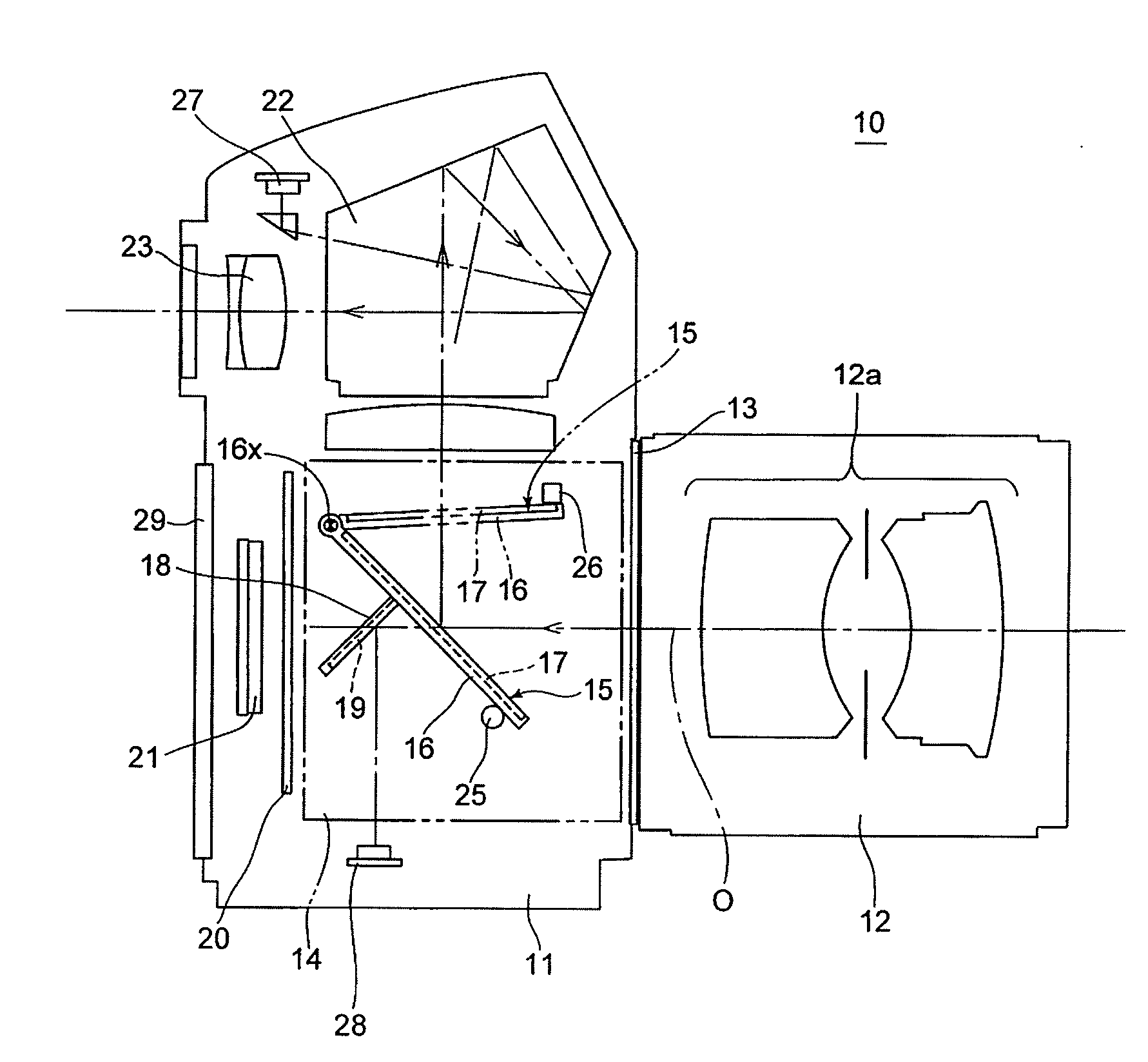
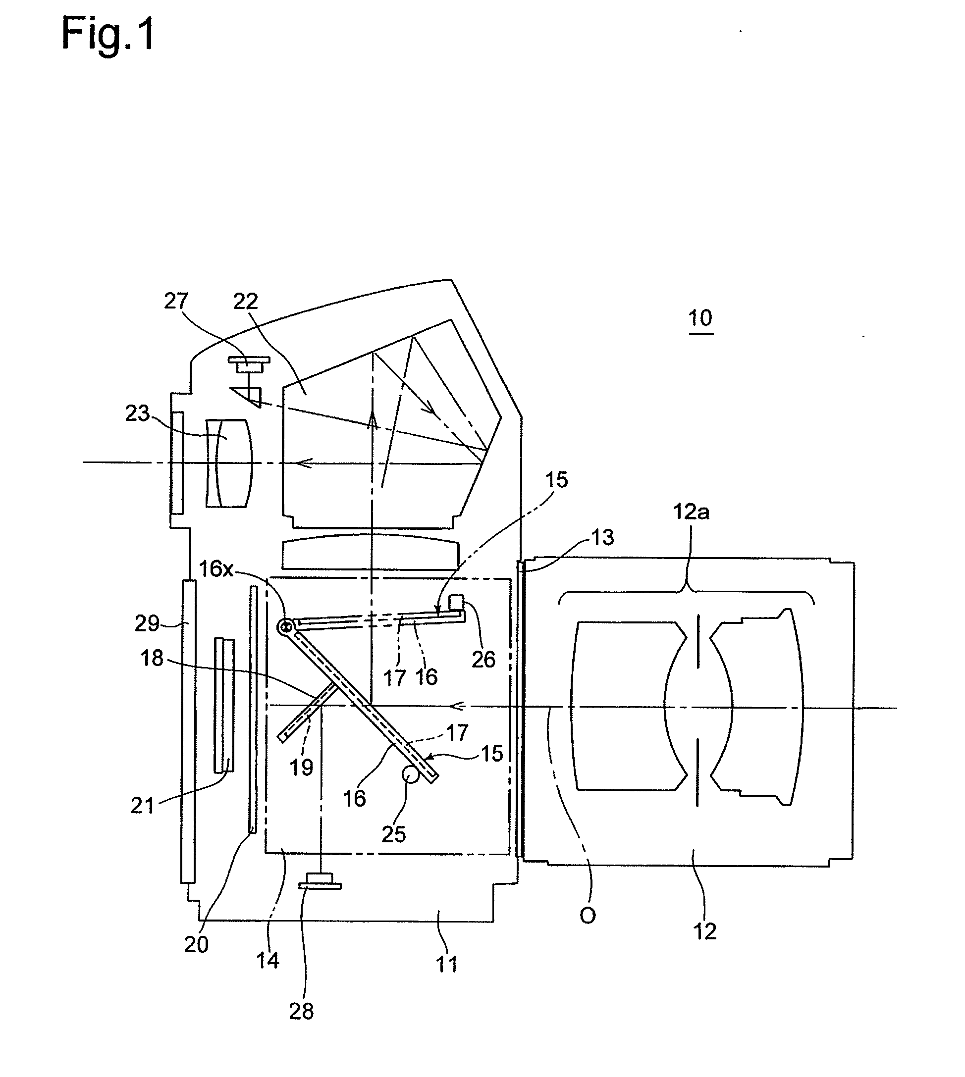
[0065]The present invention will be described below with reference to two SLR camera embodiments. FIG. 1 shows an SLR camera (hereinafter referred simply to as camera) 10 which is provided with an optical system which is common in the two embodiments of the SLR cameras. The camera 10 is provided on the front of a camera body 11 with a lens mount 13, to which an interchangeable lens 12 is detachably attached. The camera 10 is provided, in the camera body 11 behind the lens mount 13, with a mirror box 14. The camera body 11 is provided inside the mirror box 14 with a movable mirror (quick-return mirror) 15. The movable mirror 15 is provided with a main mirror 17 and a sub-mirror 19. The movable mirror 15 is constructed so that the main mirror 17 and the sub-mirror 19 are fixedly supported on a main-mirror holding frame (movable-mirror holding member / mirror seat) 16 and a sub-mirror holding frame 18, respectively, and that the sub-mirror holding frame 18 is positioned behind the main-m...


PUM


Abstract

A camera having a mirror drive mechanism, for rotating a movable mirror, includes a slider supported on a side of the movable mirror to be linearly movable in a vertical direction corresponding to an up-and-down rotation of the movable mirror, the slider including a cam follower; an end-face cam member positioned above a mirror up-and-down pivot, about which the movable mirror pivots, to be rotatable about a vertical rotational shaft, a cam follower provided on the slider is in contact with the end-face cam member so that the end-face cam member changes a vertical position of the slider via an end-face cam and the cam follower by rotating; and an end-face cam driver.
A control apparatus for a cam drive mechanism and a method of controlling a cam drive mechanism are also provided.

Description

BACKGROUND OF THE INVENTION[0001]1. Field of the Invention[0002]The present invention relates to a camera having a movable mirror for leading light emanated from an object to a viewfinder optical system, and in particular relates to a movable mirror drive mechanism and the structure of the peripheral part thereof in a camera. The present invention also relates to a control apparatus for a cam drive mechanism and a control method therefor.[0003]2. Description of the Related Art[0004]Inside SLR cameras, a movable mirror (quick-return mirror) is provided, which is capable of moving up and down; more specifically, capable of rotating between a mirror-down position (a position advanced into an optical path), in which the movable mirror is positioned in an optical path of an imaging optical system to reflect incident light emanated from an object (object-emanated light) toward a viewfinder optical system, and a mirror-up position (a position retracted from an optical path), in which the m...

Claims


Application Information

Patent Timeline
IPC IPC(8): G03B19/12
CPCG03B19/12H02K7/075H02P1/18
Inventor SANADA, SHINICHIROINAZUKA, MASAHIROKOSAKO, KOSEI
Owner RICOH IMAGING COMPANY
Why Eureka
Try Eureka