Substrate treatment process

Active Publication Date: 2015-02-12
VON ARDENNE ANLAGENTECHNIK GMBH
View PDF3 Cites 2 Cited by
  • Summary
  • Abstract
  • Description
  • Claims
  • Application Information

AI Technical Summary

Benefits of technology

[0029]Proposed for this purpose is a substrate treatment process in which there is within a chamber of the substrate treatment installation compensation for a structurally brought about input of heat into the substrate, varying periodically over the length of the chamber, during temporary dwelling of the substrate in the chamber by a substrate that is located in the chamber concerned being moved back and forth over at least one period of the heat input by a change of the transporting direction. The advantage of this process is that a homogenization

Problems solved by technology

With these active heating measures, the substrates can become very intensely heated and there is the problem that differingly hot zones form in the chambers.
This situation leads to thermal stresses in the substrates, as a consequence of which they may bend or even break.
If no allowance is made for such cases, and there is no appropriate response to them, there may be instances of bending of the subs

Method used


Image

  • Substrate treatment process
  • Substrate treatment process
  • Substrate treatment process

Examples


Embodiment Construction

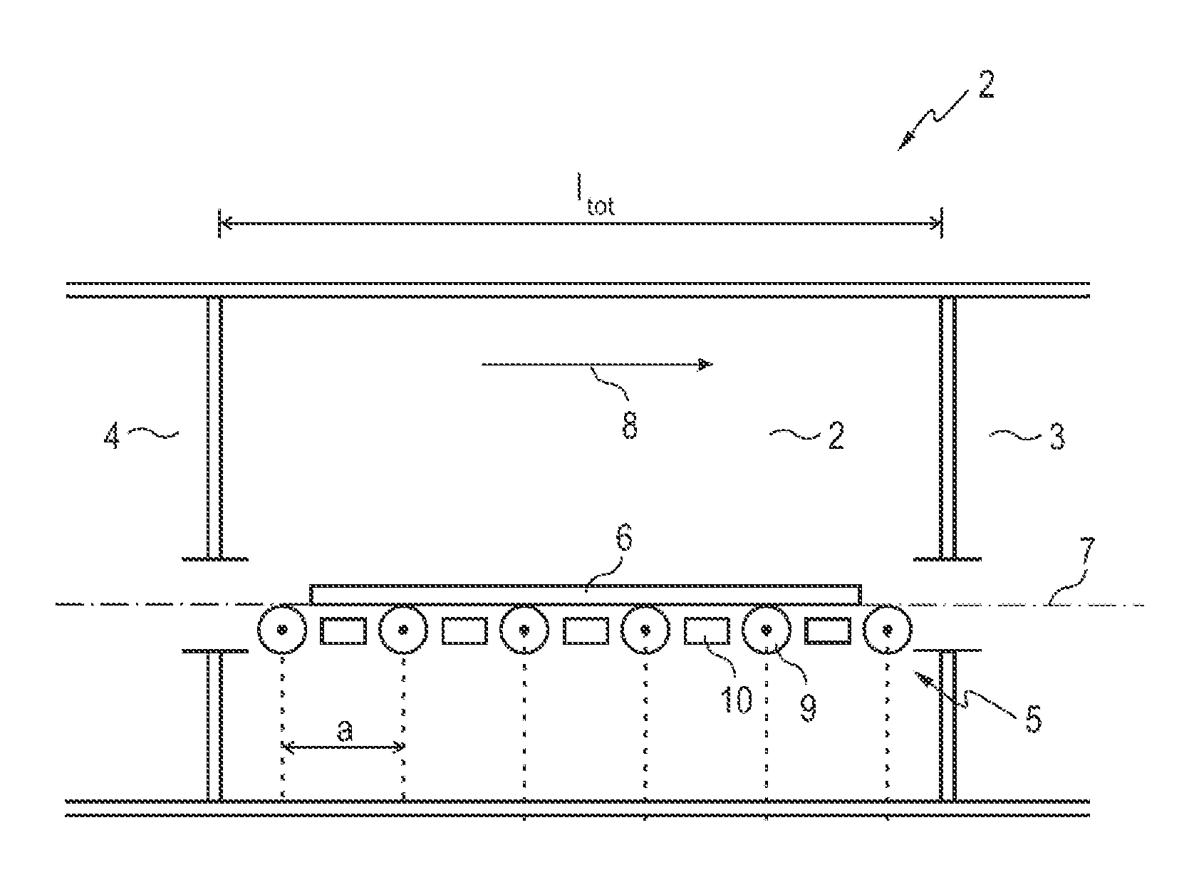
[0039]In FIG. 1, a chamber 1 of a substrate treatment installation 2, which also has further chambers 3 and 4, is schematically represented.

[0040]In this chamber 1, a transporting device 5 for transporting a substrate 6 is provided. This allows the substrate 6 to be moved in a substrate transporting plane 7 in the longitudinal direction 8.

[0041]FIG. 1 indicates a cross section through part of a substrate treatment installation 2, which consequently extends in width transversely in relation to the longitudinal direction 8, as it were through the plane of the page.

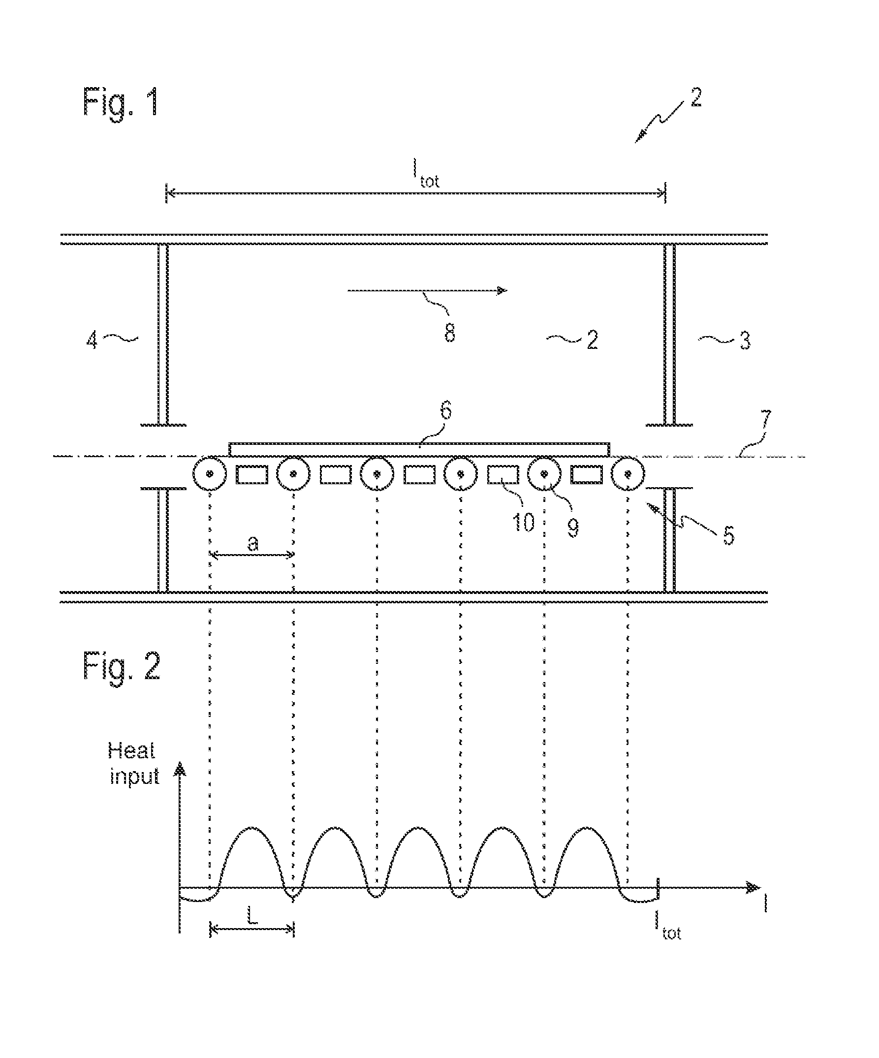
[0042]The transporting device 6 has driven transporting rollers 9, which extend longitudinally over the width of the substrate transporting plane 7, i.e. transversely in relation to the longitudinal direction of the substrate treatment installation. Arranged between the transporting rollers 9 are heaters 10, which serve for heating up the substrate 6. The alternation of transporting roller 9 and heater 10 produces a periodic...


PUM


Abstract

In a substrate treatment process, substrates are moved by a transporting device in a transporting direction through a substrate treatment installation having a number of chambers. The substrates are moved by transporting sections of the transporting device driven independently of one another. The transporting sections are driven such that, if substrates dwell temporarily in the transporting section, they are moved back and forth. Stresses in a substrate brought about by differing inputs of heat as a result of both process-induced and malfunction-induced dwell times of the substrate in a chamber are reduced by compensating within the chamber for a structurally brought about input of heat into the substrate, varying periodically over the length of the chamber, during temporary dwelling of the substrate in the chamber by moving the substrate back and forth over at least one period of the heat input by a change of the transporting direction.

Description

CROSS REFERENCE TO RELATED APPLICATIONS[0001]This application claims priority of German application No. DE 10 2013 108 449.4 filed on Aug. 6, 2013, and German application No. DE 10 2014 102 002.2 filed on Feb. 18, 2014, the entire disclosure of these applications being hereby incorporated herein by reference.BACKGROUND ART[0002]The invention relates to a substrate treatment process, in which substrates are moved by means of a transporting device in a transporting direction through a substrate treatment installation consisting of a number of chambers, the substrates being moved by way of transporting sections of the transporting device that are driven independently of one another and the transporting sections of the transporting device being driven in such a way that, if they dwell temporarily in the transporting section, substrates arranged on them are moved back and forth.[0003]A substrate treatment process should be understood here as meaning in particular a process for applying a...

Claims


Application Information

Patent Timeline
IPC IPC(8): F27B9/20F27B9/40F27B9/14
CPCF27B9/20F27B9/40F27B9/14
Inventor MOSSHAMMER, STEFFENMEYER, THOMASBRANDT, MICHAEL
Owner VON ARDENNE ANLAGENTECHNIK GMBH
Why Eureka
Try Eureka