

Spark-ignition direct fuel injection valve
a fuel injection valve and spark-ignition technology, applied in the direction of liquid fuel feeders, machines/engines, mechanical equipment, etc., can solve the problems of environmental burden, affecting the output characteristics and fuel economy of the fuel injection valve,
- Summary
- Abstract
- Description
- Claims
- Application Information
AI Technical Summary
Benefits of technology
Problems solved by technology
Method used
Image

Examples
first embodiment
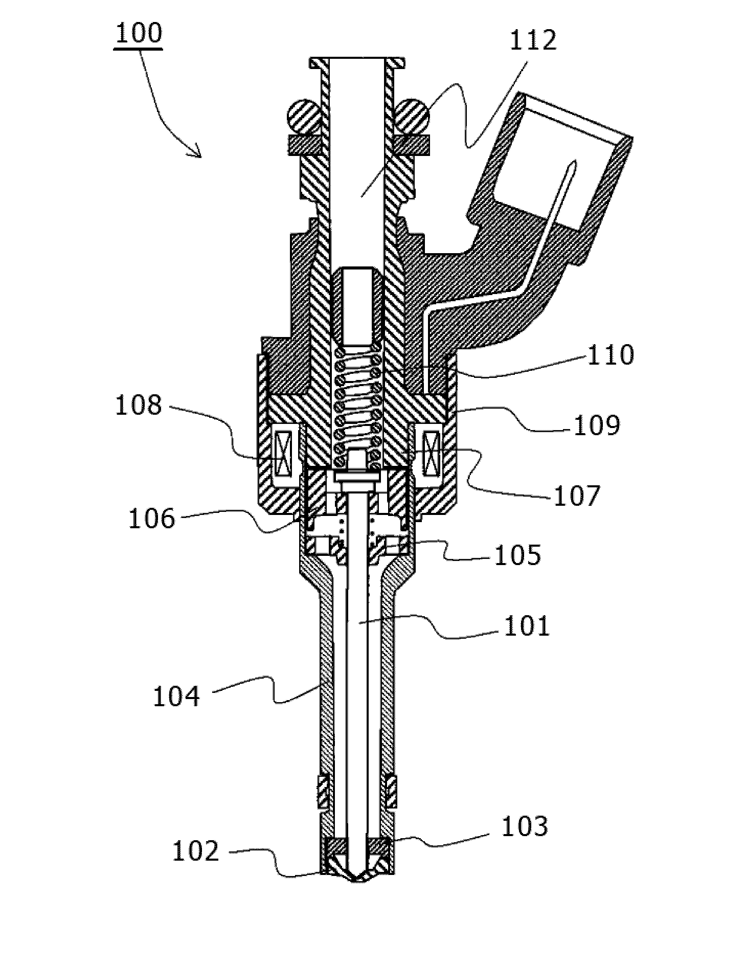
[0022]A spark-ignition direct fuel injection valve according to a first embodiment of the present invention, will be described below with reference to FIGS. 1 to 9. FIG. 1 is a sectional view of an electromagnetic fuel injection valve representing an example of a spark-ignition direct fuel injection valve of the present embodiment. The electromagnetic fuel injection valve 100 is a normally-closed, electromagnetically driven fuel injection valve used in a gasoline engine of a direct fuel injection type. When a coil 108 is de-energized, a valve body 101 is pressed against a seat member 102 by the bias force of a spring 110 thereby sealing fuel. This state is called a valve-closed state.
[0023]Fuel is supplied into the electromagnetic fuel injection valve 100 from a fuel supply port 112. For a direct fuel injection valve like the electromagnetic fuel injection valve 100, the supply fuel pressure ranges from 1 MPa to 40 MPa.
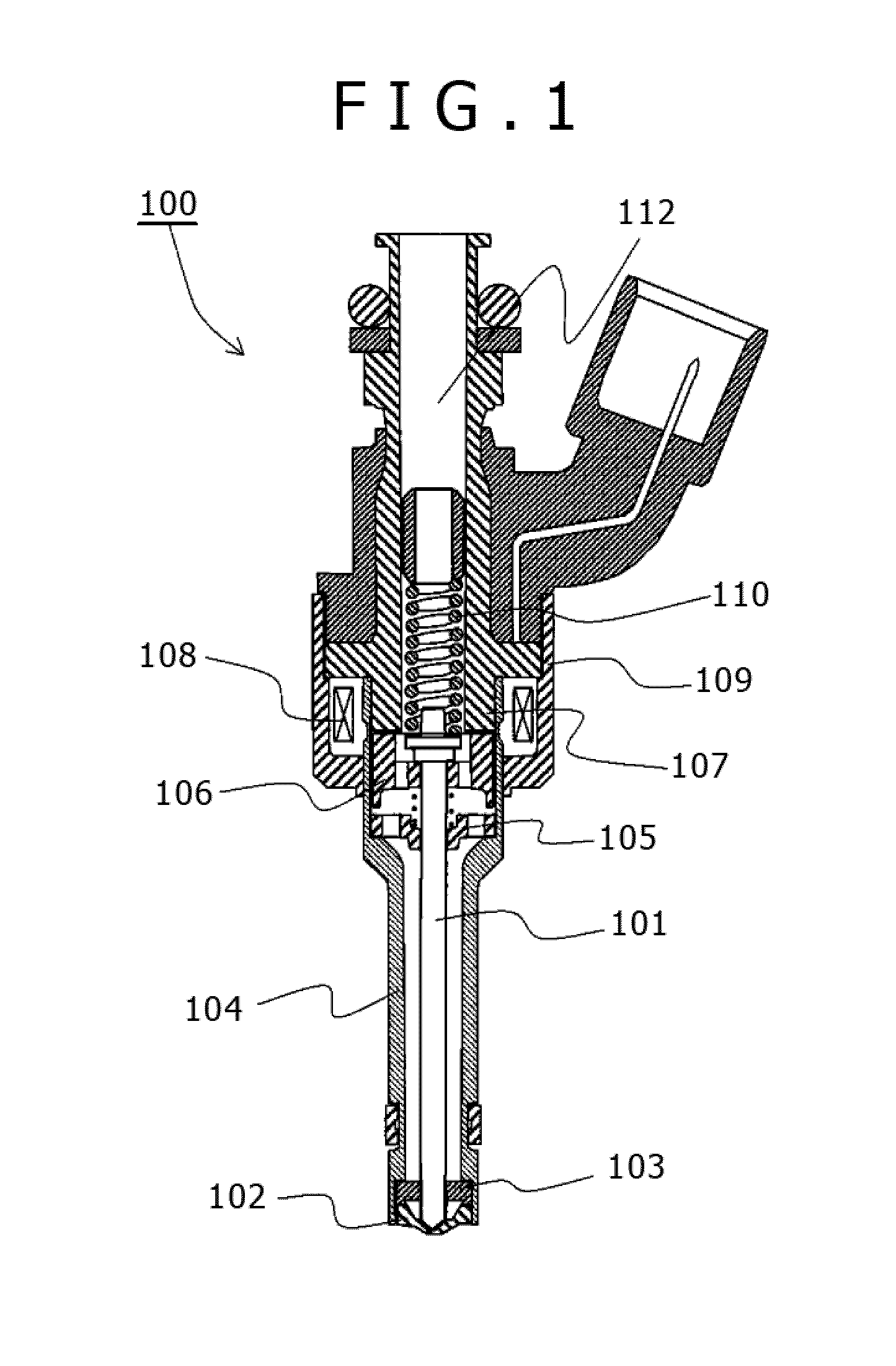
[0024]FIG. 2 is an enlarged sectional view of a vicinity of fuel...
second embodiment
[0063]A spark-ignition direct fuel injection valve according to a second embodiment of the present invention will be described below with reference to FIG. 10. In the following description, the constituent elements identical to those used in the first embodiment will be represented by the corresponding reference signs used in describing the first embodiment, and they will be described centering on differences from the first embodiment. Their aspects not particularly described in the following are the same as in the first embodiment. FIG. 10 is a sectional view showing a structure of the electromagnetic fuel injection valve 100 according to the second embodiment and corresponds to FIG. 5 (a).
[0064]In the electromagnetic injection valve 100 of the second embodiment, a side surface 1001 of each fuel injection hole is configured such that the cross-sectional area is gradually larger from the fuel injection hole inlet 304 toward the fuel injection hole outlet 305. In the second embodimen...
third embodiment
[0067]A spark-ignition direct fuel injection valve according to a third embodiment of the present invention will be described below with reference to FIG. 11. In the following description, the constituent elements identical to those used in the first embodiment will be represented by the corresponding reference signs used in describing the first embodiment, and they will be described centering on differences from the first embodiment. Their aspects not particularly described in the following are the same as in the first embodiment. FIG. 11 is a sectional view showing a structure of the electromagnetic fuel injection valve 100 according to the third embodiment and corresponds to FIG. 5 (a).
[0068]In the electromagnetic fuel injection valve 100 of the third embodiment, each fuel injection hole inlet 304 has a round-chamfered portion 1107 and each fuel injection hole outlet 305 has a round-chamfered portion 1101. A downstream end portion of the round-chamfered portion 1107 and an upstre...
PUM
 Abstract
Description
Claims
Application Information