Robot arm and robot
- Summary
- Abstract
- Description
- Claims
- Application Information
AI Technical Summary
Benefits of technology
Problems solved by technology
Method used
Image

Examples
first embodiment 1
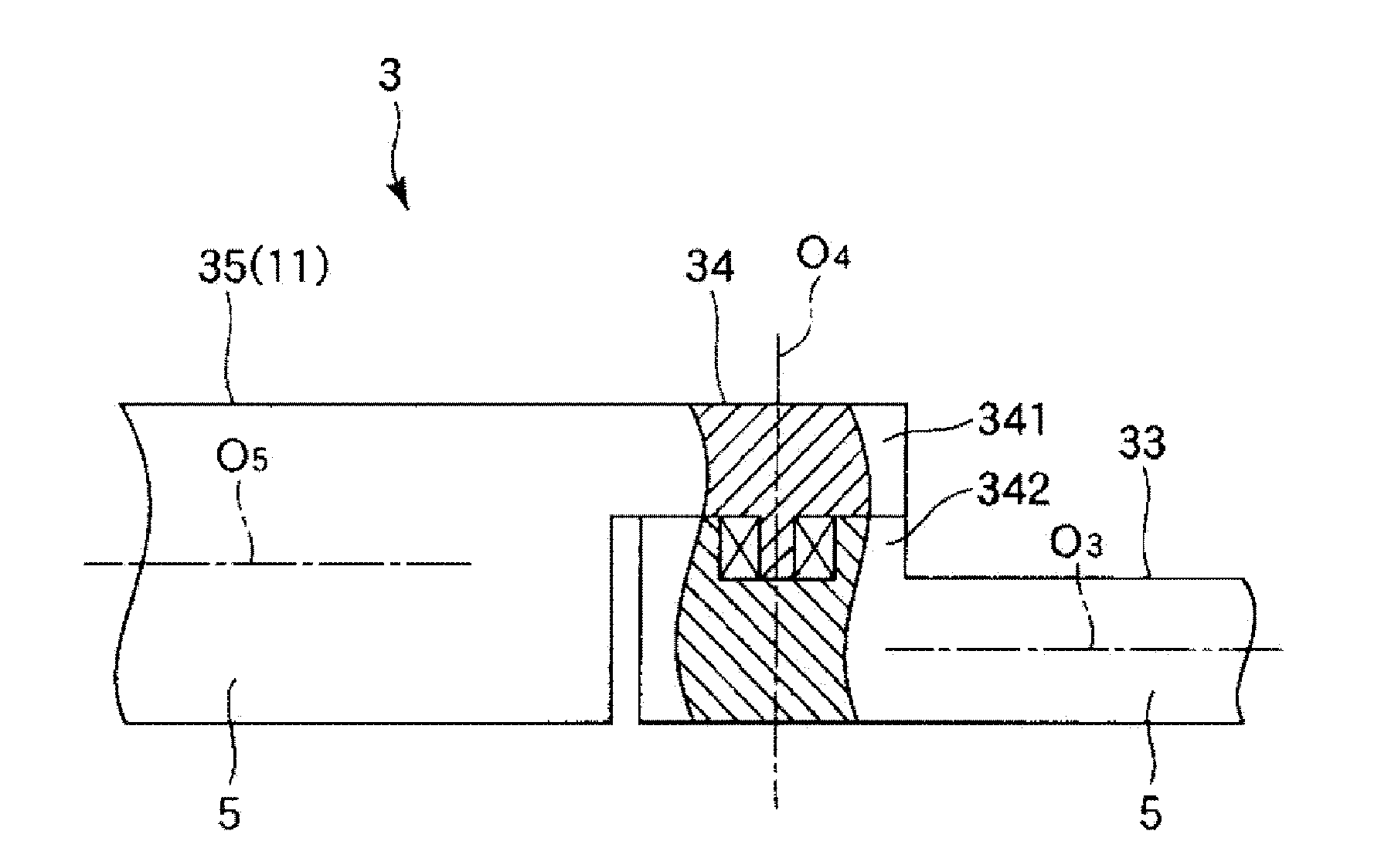
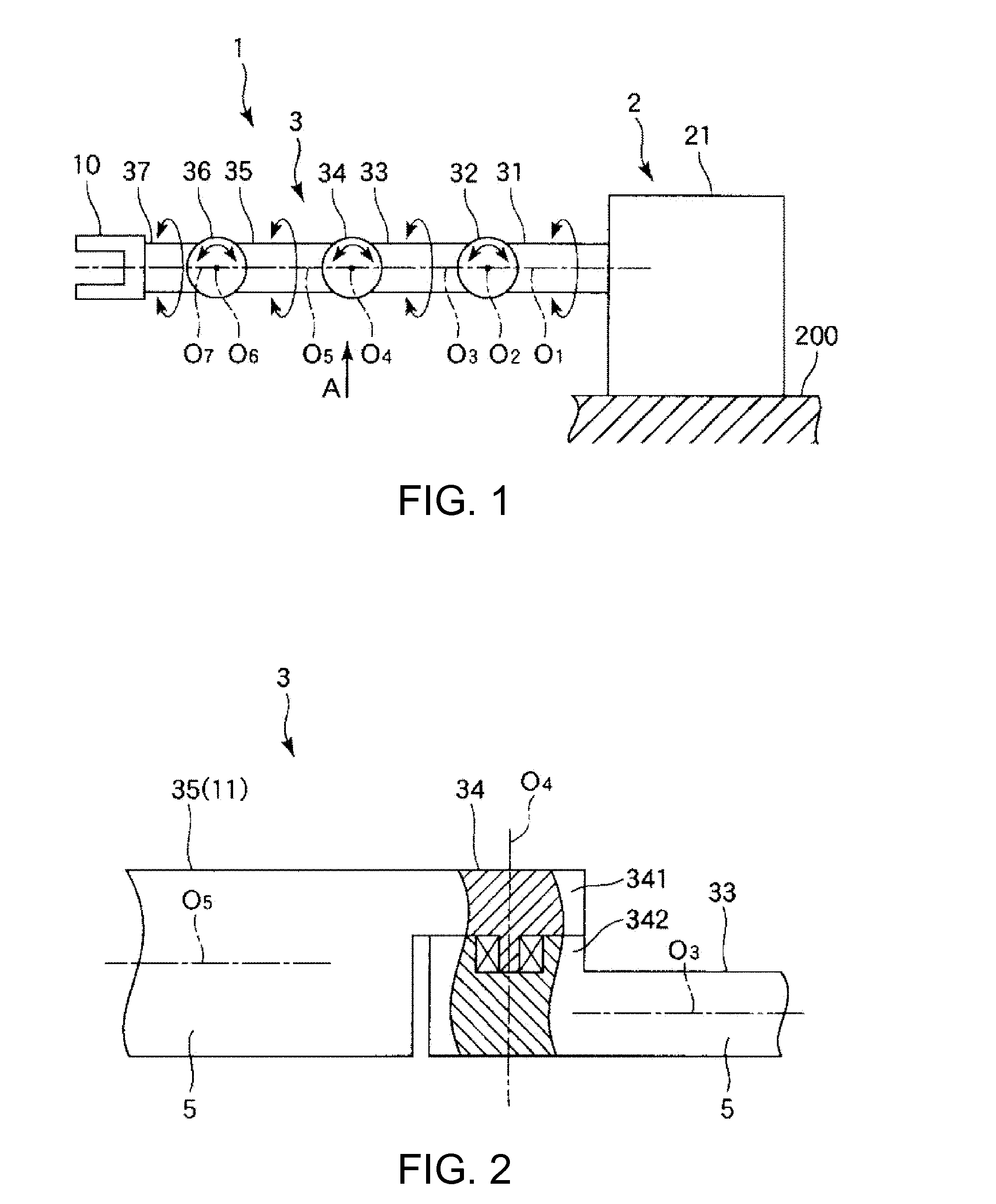
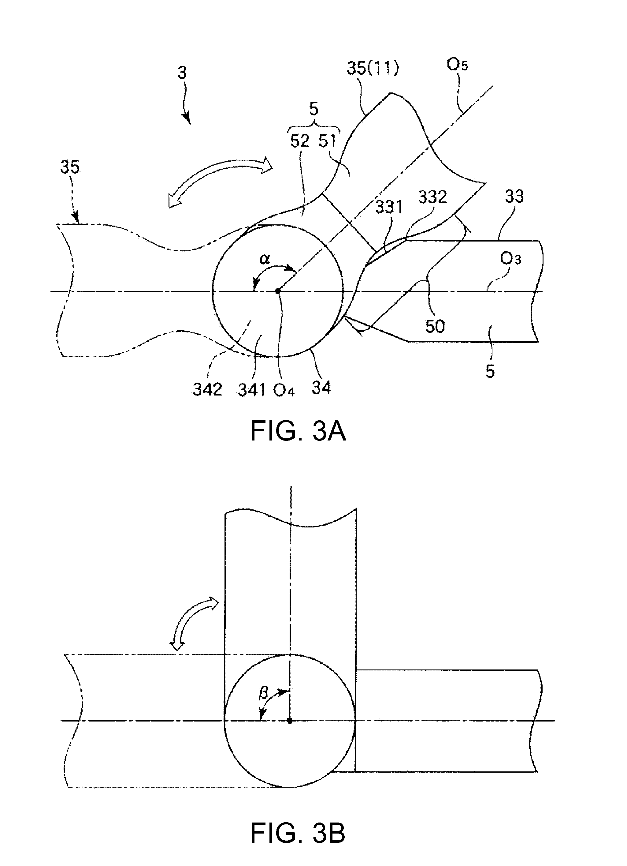
[0053]FIG. 1 is a schematic front view showing a robot including a robot arm according to this embodiment. FIG. 2 is a partial sectional view of the robot arm viewed from an arrow A direction in FIG. 1. FIGS. 3A and 3B are diagrams showing turning states of robot arms, wherein FIG. 3A is a turning state of the robot arm shown in FIG. 1 and FIG. 3B shows a turning state of a robot arm in the past. FIG. 4 is a schematic sectional view of an arm section of the robot arm shown in FIG. 1. FIGS. 5A and 5B are perspective views showing twisted states of the robot arm shown in FIG. 1, wherein FIG. 5A shows a state before twisting and FIG. 5B shows a state after the twisting. FIGS. 6A to 6C are schematic side views and schematic views from a proximal end side showing twisted states of the robot arm shown in FIG. 1, wherein FIG. 6A shows a state before twisting, FIG. 6B shows a state during the twisting, and FIG. 6C shows a state after the twisting. Note that, in the following explanation, fo...
first embodiment 2
[0108]FIG. 7 is a schematic front view showing a robot including a robot arm according to this embodiment.
[0109]The robot arm and the robot according to this embodiment are explained below with reference to the figure. However, differences from the embodiment explained above are mainly explained. Explanation of similarities is omitted.
[0110]This embodiment is the same as the first embodiment 1 except that the number of robot arms is different.
[0111]As shown in FIG. 7, in this embodiment, the robot 1 includes a plurality of robot arms 3, a body section functioning as the base 2 that supports the robot arms 3, and a camera 20 functioning as an image pickup device set on the base 2. Such a double-arm robot 1 is used in a production system of a cell production method (a variable model variable quantity production system corresponding to a demand) for assembling and manufacturing a precision apparatus (an electronic apparatus) such as a printer or a camera in end effectors 10 of the plur...
second embodiment 1
[0117]FIG. 8 is a perspective view showing an external shape of an actuator 101 according to this embodiment. FIGS. 9A and 9B are a perspective view and a sectional view showing an inside in a state in which a cylindrical outer cylinder is removed in the actuator 101 according to this embodiment.
[0118]The actuator 101 according to this embodiment is explained below with reference to the figures. However, differences from the embodiment explained above are mainly explained. Explanation of similarities is omitted.
[0119]In the actuator 101 according to this embodiment, as shown in FIG. 8, a base point link (a first link) 110 and a turning link (a second link) 111 are turnably arranged. A transmission shaft outer cylinder 112 and a reduction gear output axis outer cylinder 113 are arranged between the base point link 110 and the turning link 111. In the transmission shaft outer cylinder 112, a base point link wire body extraction port 116 is provided and a base point link fixed wire bod...
PUM
| Property | Measurement | Unit |
|---|---|---|
| Length | aaaaa | aaaaa |
| Diameter | aaaaa | aaaaa |
Abstract
Description
Claims
Application Information
 - R&D
- Intellectual Property
- Life Sciences
- Materials
- Tech Scout
- Unparalleled Data Quality
- Higher Quality Content
- 60% Fewer Hallucinations
Browse by: Latest US Patents, China's latest patents, Technical Efficacy Thesaurus, Application Domain, Technology Topic, Popular Technical Reports.
© 2025 PatSnap. All rights reserved.Legal|Privacy policy|Modern Slavery Act Transparency Statement|Sitemap|About US| Contact US: help@patsnap.com