
Annular barrier with a seal

a technology of annular barrier and seal, which is applied in the field of annular barrier with seal, can solve the problems of minor minimisation of the size of the barrier, affecting compromising so as to achieve the effect of increasing the quality of the seal

Active Publication Date: 2015-03-12
WELLTEC OILFIELD SOLUTIONS AG
View PDF1 Cites 30 Cited by
  • Summary
  • Abstract
  • Description
  • Claims
  • Application Information

AI Technical Summary

Benefits of technology

The present invention provides an improved downhole annular barrier that can better seal the well and prevent leaks. The invention solves problems with previous annular barriers by minimizing the expandable part that can occur when the injection of pressurized fluid ends, and by keeping the pressure exerted by the sealing element on the inner surface of the outer structure. This results in a better quality seal and increased safety in the well.

Problems solved by technology

Therefore, a certain level of fluid leaking into or away from the sealed of zone is typically allowed and acceptable, but the quality of the seal is compromised if too much fluid can pass the seal.
Also, other settling effects, such as pressure equalisation in the annular barrier, may cause a minor minimisation of the size of the barrier.
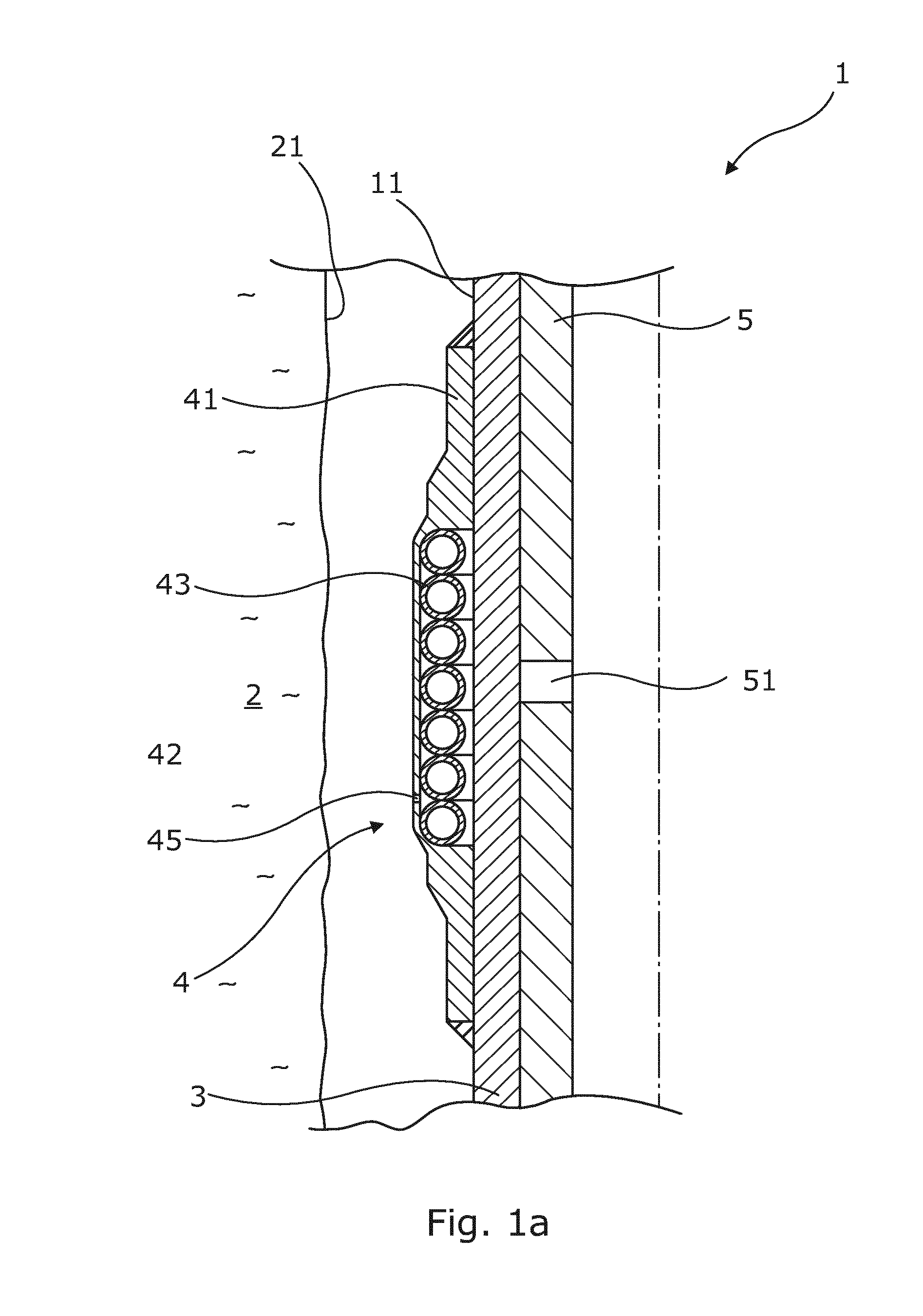
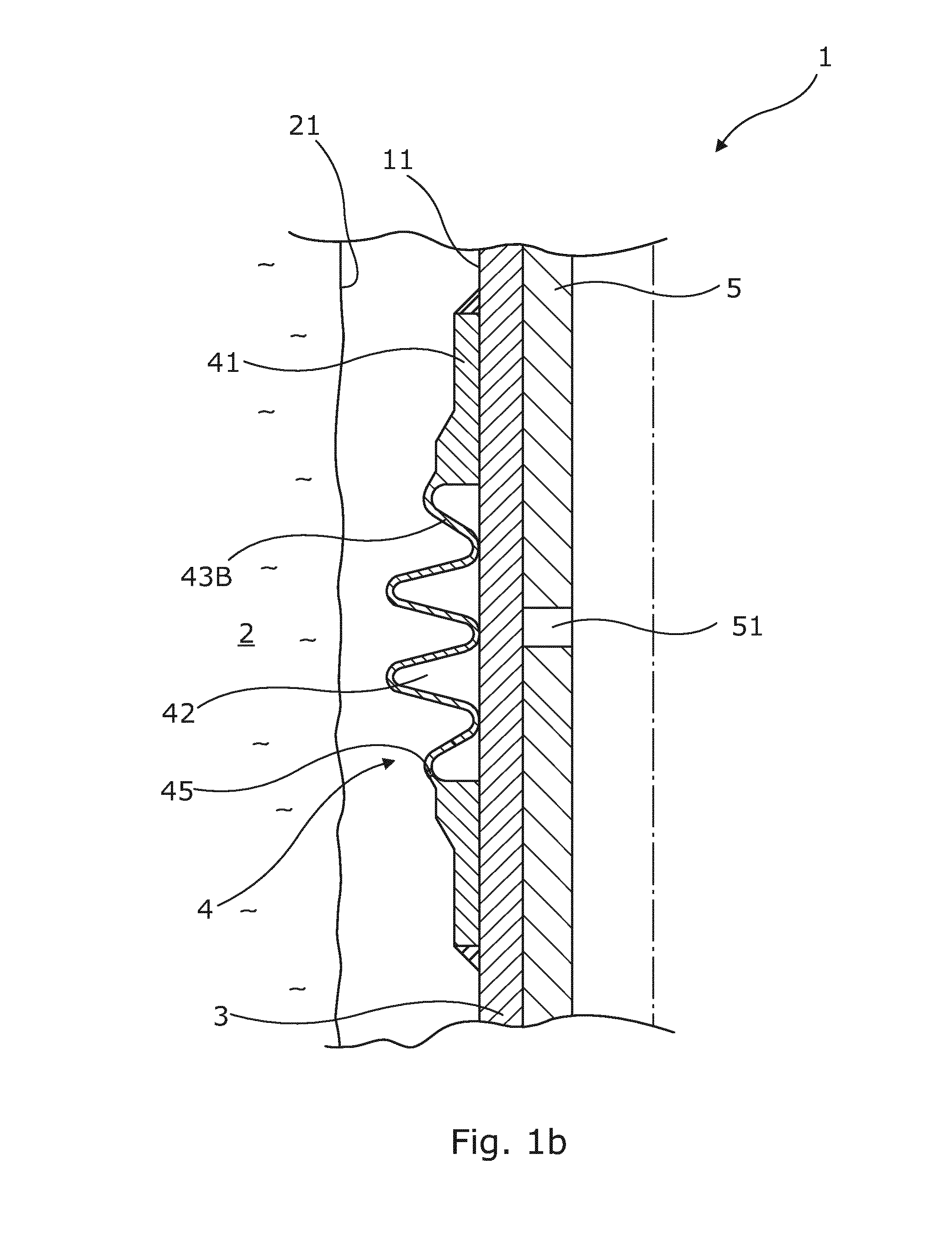
The spring back effect of the expandable part negatively affects the quality of the seal provided by the downhole annular barrier 1, since the seal becomes poorer after expansion in terms of tightness or the amount of fluid possibly passing the seal.

Method used


Image

  • Annular barrier with a seal
  • Annular barrier with a seal
  • Annular barrier with a seal

Examples


Embodiment Construction

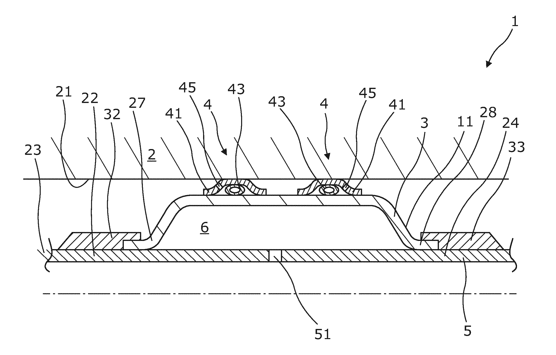
[0077]Downhole annular barriers 1 according to the present invention are typically mounted as part of the well tubular structure string before the well tubular structure 23 is lowered into the borehole downhole, as shown in the cross-sectional view of one downhole annular barrier in FIG. 2. The well tubular structure 23 is constructed by well tubular structure parts put together as a long well tubular structure string. Often, the annular barriers are mounted in between the well tubular structure parts when the well tubular structure string is mounted.

[0078]The downhole annular barrier 1 is used for a variety of purposes, all of which require that an expandable part 3 of the downhole annular barrier 1 is expanded, so that an outer surface 11 of the downhole annular barrier 1 abuts an inner surface 21 of an outer structure 2, such as a borehole casing or a formation surrounding a borehole. The downhole annular barrier 1 has an axial extension parallel to the direction of the borehole ...


PUM


Abstract

The present invention relates to a downhole annular barrier (1) with an axial extension having an outer surface facing an inner surface of an outer structure (2). The downhole annular barrier comprises a tubular part (5), an expandable part (3), and at least one annular sealing element (41). The annular sealing element (41) is connected with the expandable part (3) and has an axial length along the axial extension of the downhole annular barrier which is less than 50% of a length of the downhole annular barrier along the axial extension of the downhole annular barrier. The annular sealing element comprises a spring element (43). Also, the present invention relates to a downhole system and to a seal providing method.

Description

FIELD OF THE INVENTION[0001]The present invention relates to a downhole annular barrier with an axial extension having an outer surface facing an inner surface of an outer structure, comprising a tubular part, an expandable part, and at least one annular sealing element. Also, the present invention relates to a downhole system and to a seal providing method.BACKGROUND ART[0002]In wellbores, downhole annular barriers are used for different purposes, such as for providing a barrier for flow between an inner and an outer tubular structure or between an inner tubular structure and the inner wall of the borehole. The downhole annular barriers are mounted as part of the well tubular structure. A downhole annular barrier has an inner wall surrounded by an annular expandable sleeve. The expandable sleeve is typically made of an elastomeric material, but may also be made of metal. The sleeve is fastened at its ends to the inner wall of the downhole annular barrier.[0003]In order to seal off ...

Claims


Application Information

Patent Timeline
Patent Type & Authority Applications(United States)
IPC IPC(8): E21B33/127
CPCE21B33/1277E21B33/127E21B33/1212
Inventor HALLUNDB.AE BUTTED.K, JORGENST.AE BUTTED.HR, LARS
Owner WELLTEC OILFIELD SOLUTIONS AG
Learn More