Private ethernet overlay networks over a shared ethernet in a virtual environment
What is AI technical title?
AI technical title is built by Patsnap AI team. It summarizes the technical point description of the patent document.
a virtual environment and private ethernet technology, applied in data switching networks, digital transmission, electrical equipment, etc., can solve the problems of reducing the scalability of the entire distributed system, sending a broadcast message in a private network, and complex problems such as the inability to impose a private network on a distributed environment encompassing multiple physical networks
Active Publication Date: 2015-03-12
NICIRA
View PDF11 Cites 65 Cited by
Summary
Abstract
Description
Claims
Application Information
AI Technical Summary
This helps you quickly interpret patents by identifying the three key elements:
Problems solved by technology
Method used
Benefits of technology
Problems solved by technology
Trying to impose a private network on a distributed environment encompassing multiple physical networks is a complex problem.
Further, sending a broadcast message in a private network presents two problems.
First, the broadcast may be received by hosts which do not host any VMs in the private network, thus reducing the scalability of the entire distributed system.
Second, if hosts are not located on adjacent layer 2 networks, the broadcast may not reach all hosts with VMs in the private network.
However, VLANs only offer encapsulation and, by definition, switches may not bridge traffic between VLANs as it would violate the integrity of the VLAN broadcast domain.
Further, VLANs are not easily programmable by a centralized virtual infrastructure manager.
However, these environments often have network configurations that when deployed multiple times would cause networking routing problems, such as the creation of VMs with duplicate Internet Protocol (IP) addresses--an impermissible network scenario for the proper operation of the VMs and of the virtual lab environments.
However, the single-host implementation has drawbacks, such as a maximum number of VMs that can be deployed on a single host, inability to move VMs to different hosts for load balancing, unexpected host shutdowns, etc.
Method used
Image
Click on the blue label to locate the original text in one second.
Reading with bidirectional positioning of images and text.
Examples
Embodiment Construction
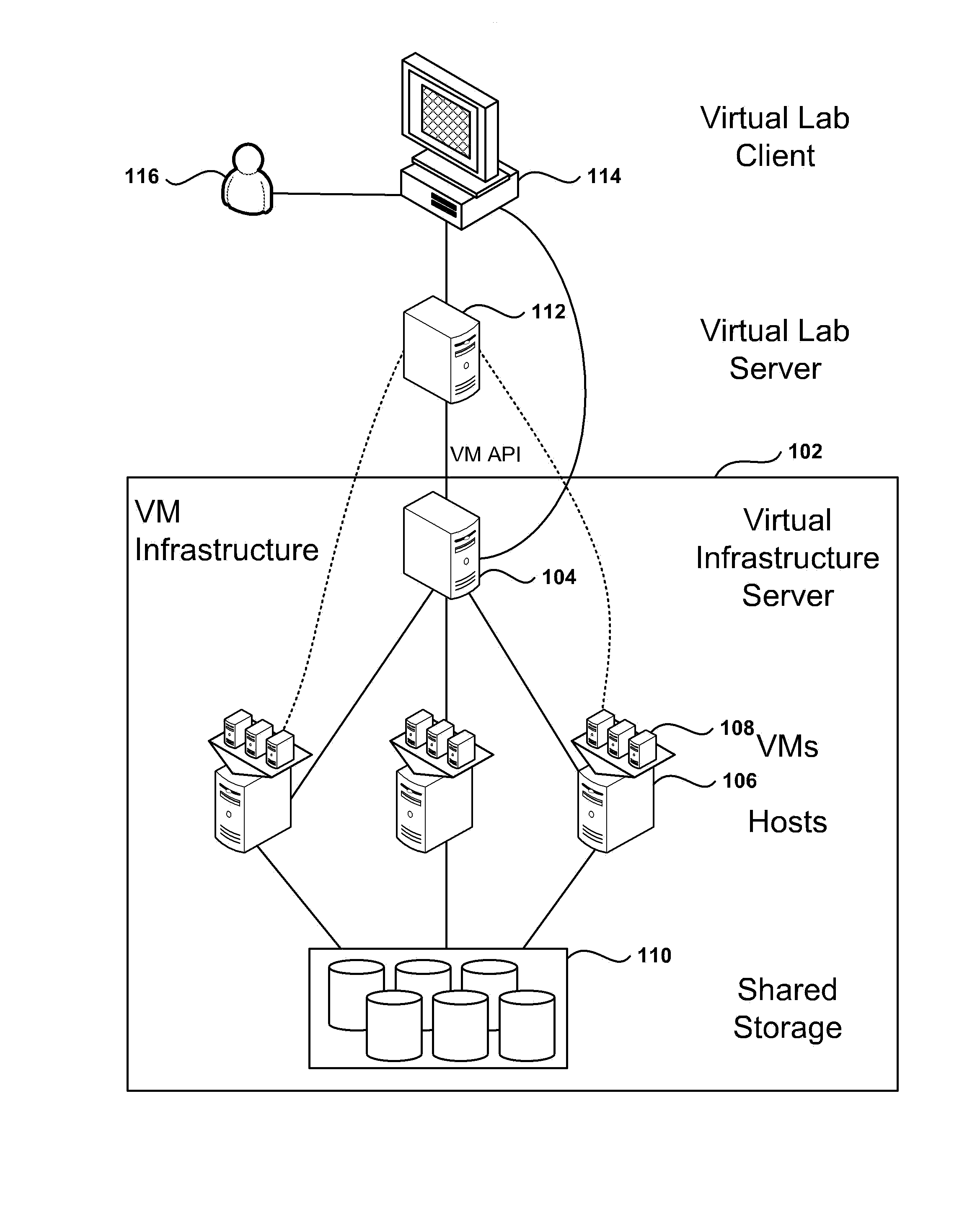
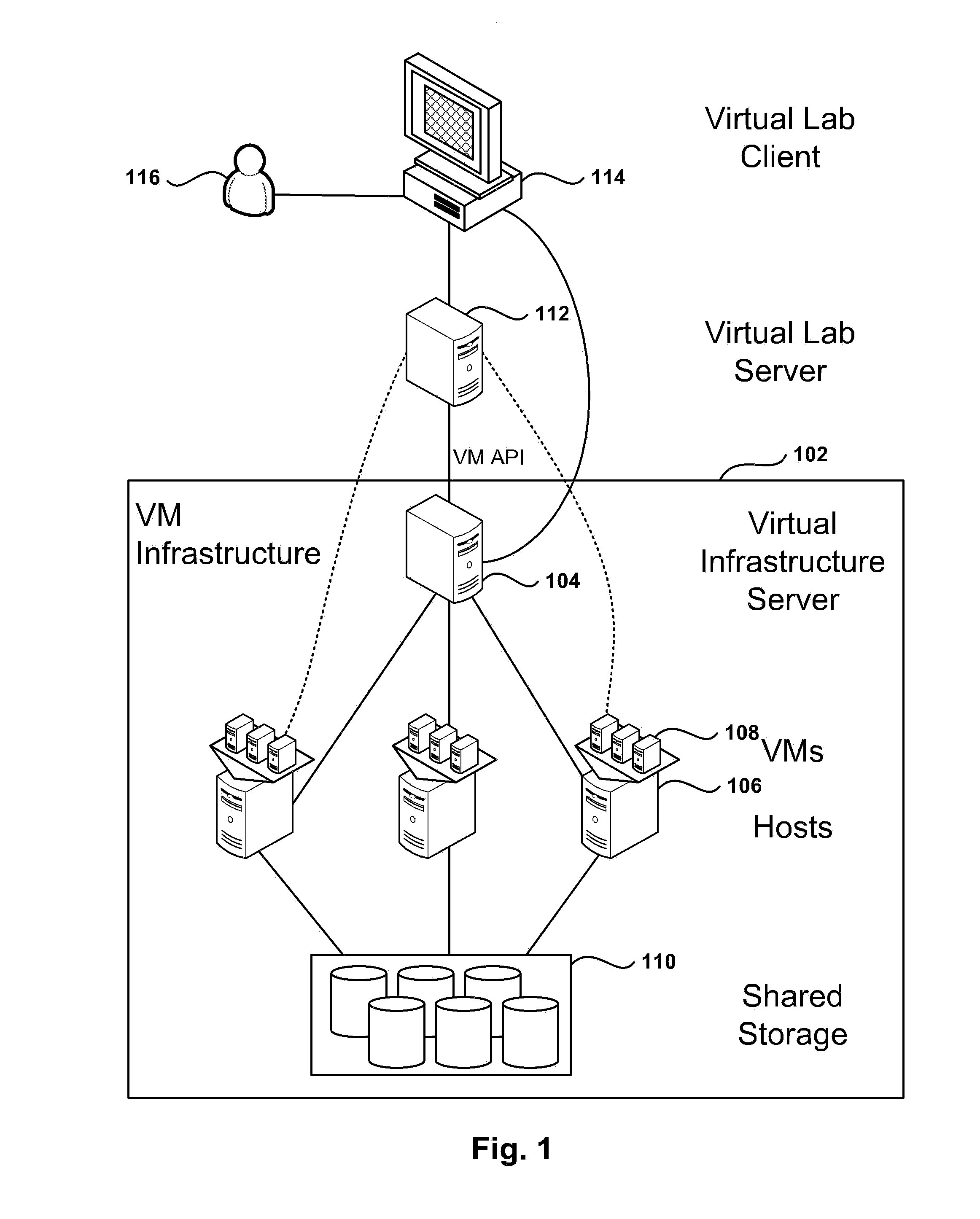
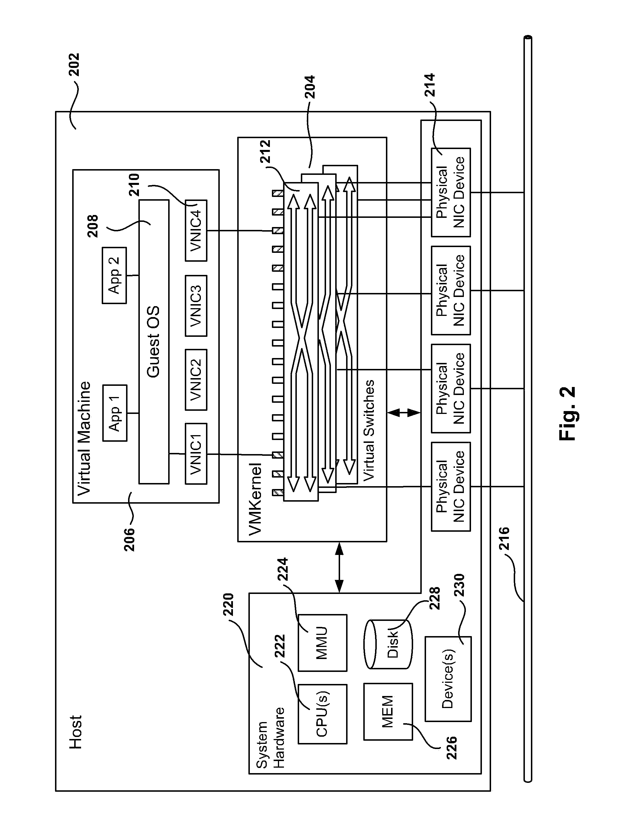
[0031]The following embodiments describe methods and apparatus for implementing private networking within a virtual infrastructure. Embodiments of the invention use Media Access Control (MAC) encapsulation of Ethernet packets. The hosts that include Virtual Machines (VM) from fenced groups of machines implement distributed switching with learning for unicast delivery. As a result, VMs are allowed to migrate to other hosts to enable resource management and High Availability (HA). Further, the private network implementation is transparent to the guest operating system (GOS) in the VMs and provides an added level of privacy.
[0032]With a host-spanning private network (HSPN), VMs can be placed on any host where the private network is implemented. The HSPN may span hosts in a cluster or clusters in a datacenter, allowing large groups of VMs to communicate over the private network. Additionally, VMs may move between hosts since VMs maintain private network connectivity. A VM can also be po...
PUM
Abstract
A system for private networking within a virtual infrastructure is presented. The system includes a virtual machine (VM) in a first host, the VM being associated with a first virtual network interface card (VNIC), a second VM in a second host, the second VM being associated with a second VNIC, the first and second VNICs being members of a fenced group of computers that have exclusive direct access to a private virtual network, wherein VNICs outside the fenced group do not have direct access to packets on the private virtual network, a filter in the first host that encapsulates a packet sent on the private virtual network from the first VNIC, the encapsulation adding to the packet a new header and a fence identifier for the fenced group, and a second filter in the second host that de-encapsulates the packet to extract the new header and the fence identifier.
Description
CROSS REFERENCE TO RELATED APPLICATIONS[0001]This application is a Divisional of U.S. patent application Ser. No. 12 / 819,438 filed Jun. 21, 2010, issued as U.S. Pat. No. 8,892,706, which is hereby incorporated by reference.[0002]This application is related by subject matter to U.S. patent application Ser. No. 12 / 510,072, filed Jul. 27, 2009, and entitled “AUTOMATED NETWORK CONFIGURATION OF VIRTUAL MACHINES IN A VIRTUAL LAB ENVIRONMENT”; U.S. patent application Ser. No. 12 / 510,135, filed Jul. 27, 2009, and entitled “MANAGEMENT AND IMPLEMENTATION OF ENCLOSED LOCAL NETWORKS IN A VIRTUAL LAB”; and U.S. patent application Ser. No. 12 / 571,224, filed Sep. 30, 2009, and entitled “PRIVATE ALLOCATED NETWORKS OVER SHARED COMMUNICATIONS INFRASTRUCTURE”; U.S. patent application Ser. No. 11 / 381,119, filed May 1, 2006, and entitled “VIRTUAL NETWORK IN SERVER FARM”, all of which are incorporated herein by reference.FIELD OF THE INVENTION[0003]The present invention relates to methods, systems, and c...
Claims
Application Information
Patent Timeline
Application Date:The date an application was filed.
Publication Date:The date a patent or application was officially published.
First Publication Date:The earliest publication date of a patent with the same application number.
Issue Date:Publication date of the patent grant document.
PCT Entry Date:The Entry date of PCT National Phase.
Estimated Expiry Date:The statutory expiry date of a patent right according to the Patent Law, and it is the longest term of protection that the patent right can achieve without the termination of the patent right due to other reasons(Term extension factor has been taken into account ).
Invalid Date:Actual expiry date is based on effective date or publication date of legal transaction data of invalid patent.
Patent Type & AuthorityApplications(United States)

