
Address resolution mechanism for ethernet maintenance endpoints

a resolution mechanism and endpoint technology, applied in the field of data communication systems, can solve the problems of bbng terminating associated service vlans (s-vlans) and service/customer vlan combinations having difficulty intercepting ccms, and it is difficult, if not impossible, for a sp network administrator or operator to check,

Active Publication Date: 2007-01-18
CISCO TECH INC
View PDF97 Cites 214 Cited by
  • Summary
  • Abstract
  • Description
  • Claims
  • Application Information

AI Technical Summary

Problems solved by technology

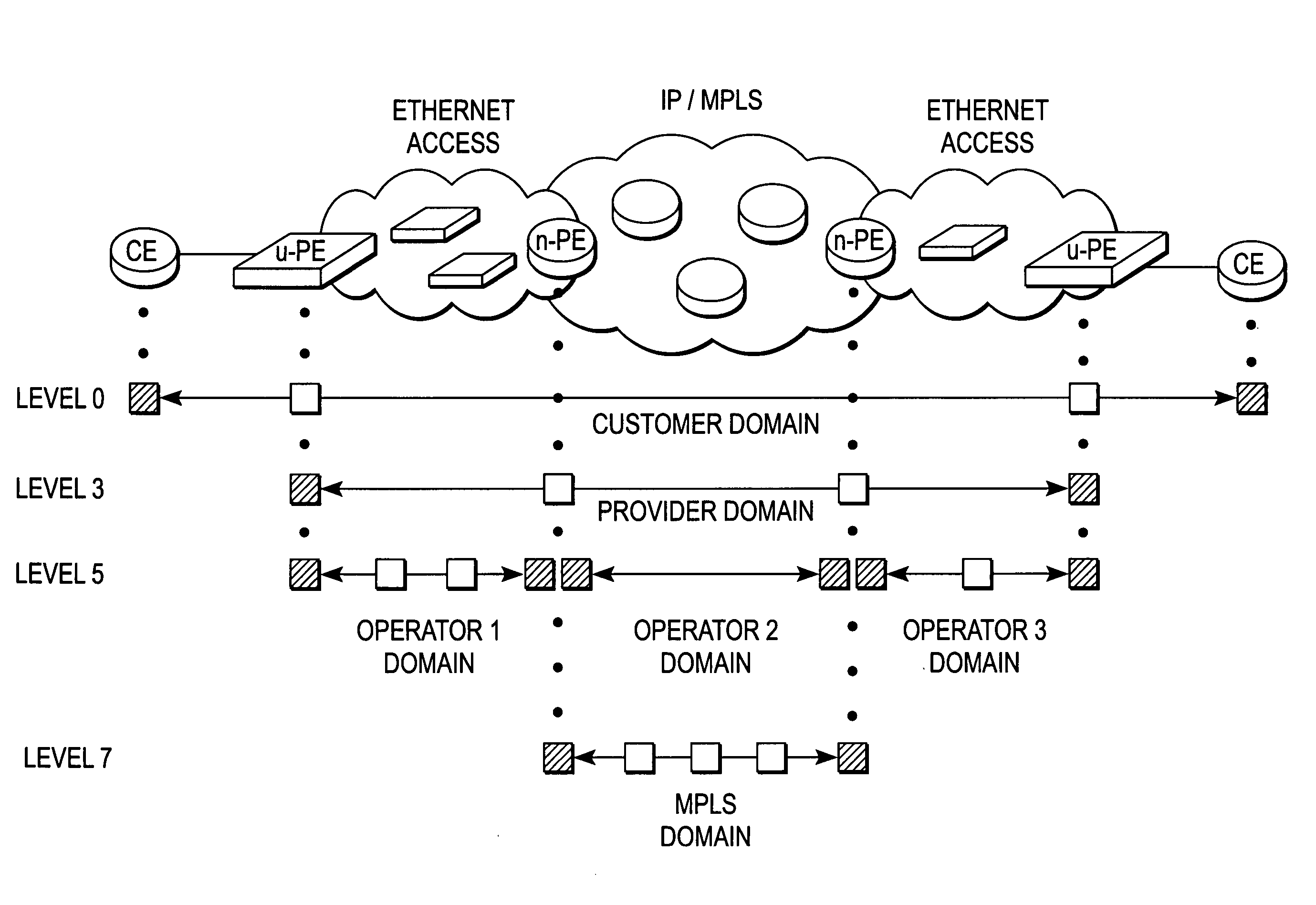
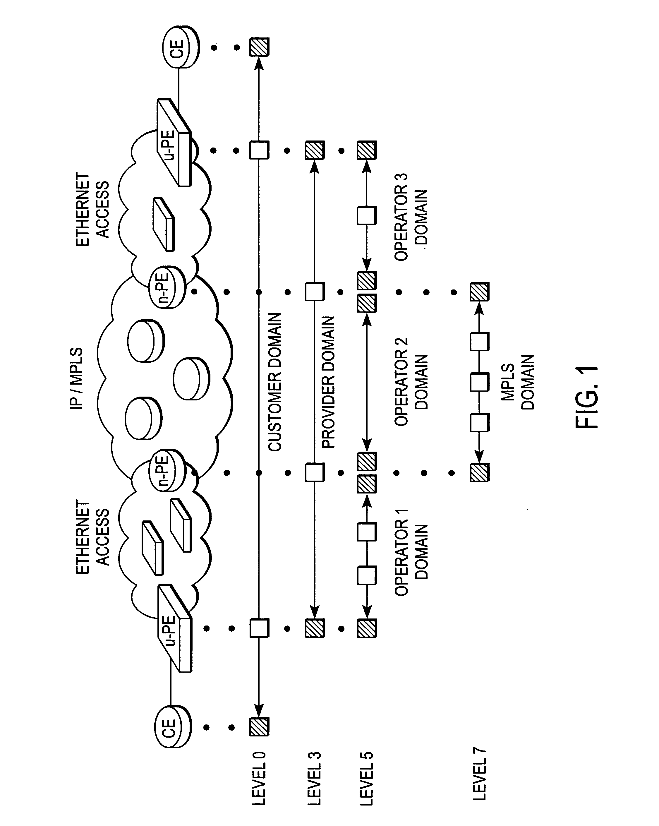
One of the drawbacks of Ethernet CFM as defined in 802.1ag is that it presumes that every node in the network (CE-to-CE in FIG. 1) supports the full set of functionalities defined in that specification.
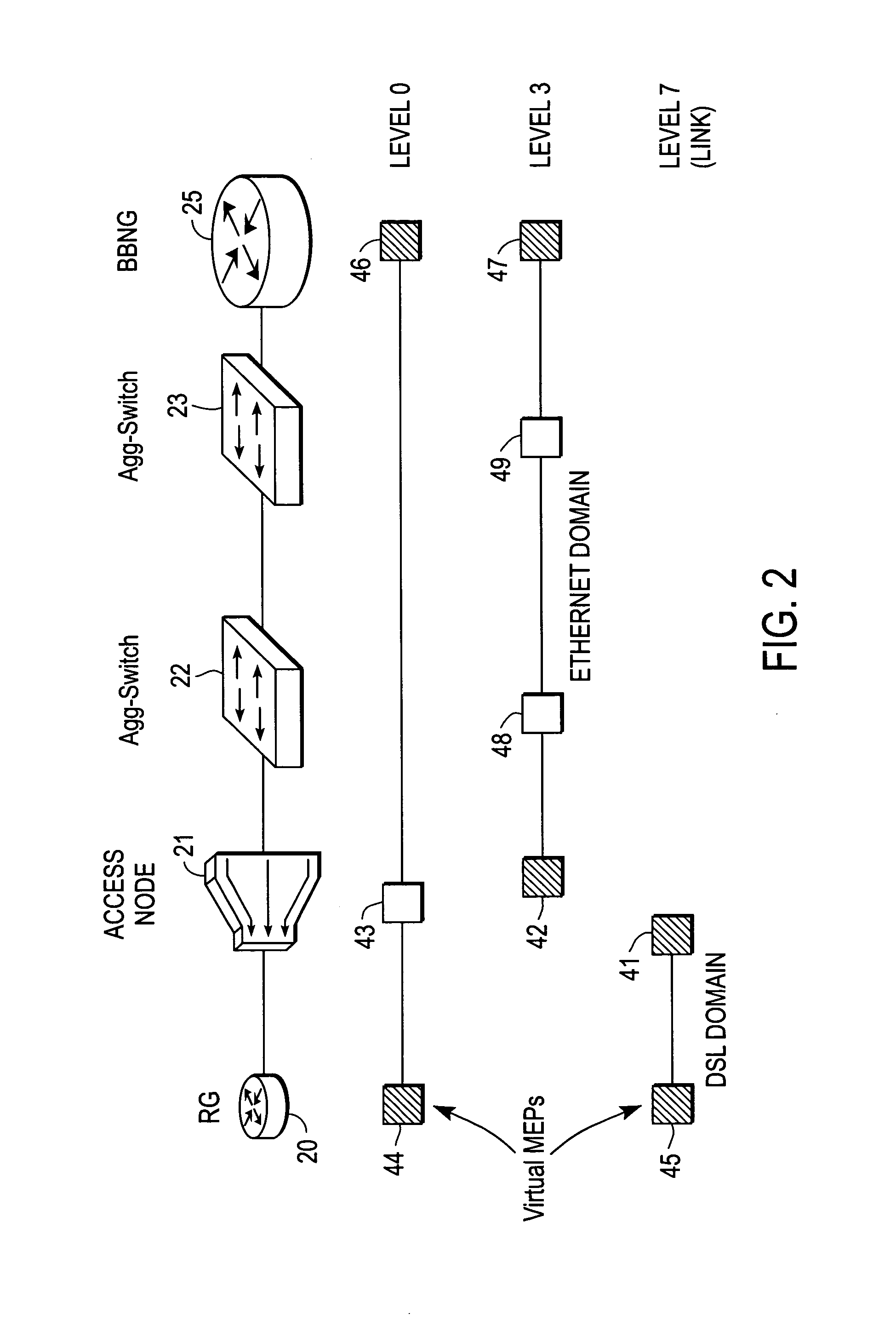
The problem, however, is that for broadband access the service terminating node at the customer premises equipment (CPE) typically does not have a MAC address or the ability to run the full protocol suite defined in the 802.1ag standard.
This makes it very difficult, if not impossible, for a SP network administrator or operator to check the physical connection path that data packets take between the RG and the BBNG nodes in response to, say, a service complaint received from a subscriber with an ATM connection to a DSLAM device.
But in the case where there are tens of thousands of users logically connected to a single VLAN, multicasting CCMs by each MEP can result in a flood of messaging that overwhelms network resources.
In addition, the BBNG terminating associated Service VLANs (S-VLANs) and Service / Customer VLAN (S / C-VLAN) combinations might have difficulty intercepting the CCMs.
However, this creates a new problem since those messages convey address information about a given user port, thus making it difficult to transmit a message to a target port from a remote part of the network.
Further complicating the use of 802.1ag for issuing OAM functions in an Ethernet DSL environment is the fact that many SPs consider it to be too operationally complex to maintain a database of customer-id to the MAC address assigned to each user port of the DSLAM.

Method used


Image

  • Address resolution mechanism for ethernet maintenance endpoints
  • Address resolution mechanism for ethernet maintenance endpoints
  • Address resolution mechanism for ethernet maintenance endpoints

Examples


Embodiment Construction

[0021] A multicast-based mechanism for resolving the address of a user-line MEP (i.e., its MAC address and MEP-ID), which obviates the need for address advertising CCMs, is described. In the following description specific details are set forth, such as device types, protocols, configurations, etc., in order to provide a thorough understanding of the present invention. However, persons having ordinary skill in the networking arts will appreciate that these specific details may not be needed to practice the present invention.

[0022] A computer network is a geographically distributed collection of interconnected subnetworks for transporting data between nodes, such as intermediate nodes and end nodes. A local area network (LAN) is an example of such a subnetwork; a plurality of LANs may be further interconnected by an intermediate network node, such as a router, bridge, or switch, to extend the effective “size” of the computer network and increase the number of communicating nodes. Exa...


PUM


Abstract

A method of operation for a node of an Ethernet access network includes issuing a multicast message on the Ethernet access network by a maintenance end point (MEP) of the node. The multicast message contains a name of a target MEP. The node is further operable to receive a unicast reply message from the target MEP, the unicast message reply containing a MEP identifier (MEP-ID) and a MEP Media Access Control (MAC) address of the target MEP. It is emphasized that this abstract is provided to comply with the rules requiring an abstract that will allow a searcher or other reader to quickly ascertain the subject matter of the technical disclosure. It is submitted with the understanding that it will not be used to interpret or limit the scope or meaning of the claims.

Description

RELATED APPLICATIONS [0001] The present application is related to concurrently filed application serial no. ______, entitled, “Broadband Access Node With A Virtual Maintenance End Point”, which is assigned to the assignee of the present application.FIELD OF THE INVENTION [0002] The present invention relates generally to data communications systems; more specifically, to service provider (SP) networks with Ethernet access domains that support Operations and Management (OAM) functions. BACKGROUND OF THE INVENTION [0003] Digital Subscriber Line (DSL) technology is widely-used today for increasing the bandwidth of digital data transmissions over the existing telephone network infrastructure. In a typical system configuration, a plurality of DSL subscribers are connected to a service provider (SP) network through a Digital Subscriber Line Access Multiplexer (DSLAM), which concentrates and multiplexes signals at the telephone service provider location to the broader wide area network (WAN...

Claims


Application Information

Patent Timeline
IPC IPC(8): H04L12/56H04L12/28
CPCH04L12/2856H04L12/2859H04L12/2861H04L61/103H04L29/12028H04L43/0811H04L43/10H04L12/2881
Inventor DEC, WOJCIECHHERTOGHS, YVESFINN, NORMAN W.
Owner CISCO TECH INC
Learn More