Supercharge Your Innovation With Domain-Expert AI Agents!

Method of Assembling An Electrical Terminal Assembly

a technology of electrical terminals and assembly methods, applied in the field of electrical terminals, can solve the problems of loss of spring force, copper is susceptible to relaxation, and the overall contact area is affected

Active Publication Date: 2015-03-19
LEAR CORP
View PDF9 Cites 14 Cited by
  • Summary
  • Abstract
  • Description
  • Claims
  • Application Information

AI Technical Summary

Benefits of technology

This patent is about a special way of making electrical terminals. It involves connecting two parts called a base and a spring member. The base has beams that stick out from it, and the spring member has beams that stick out from it. The two parts are put together and the parts' beams make contact with each other. This makes a connection that can be easily disconnected and reassembled. The technical effect of this invention is to make electrical terminals that are easier to assemble and modify.

Problems solved by technology

However, copper is susceptible to relaxation (i.e., loss of spring force) as the temperature of the copper material increases.
Relaxation of the female terminals may decrease the overall contact area with the male blades, resulting in reduced electrical conductivity, increased resistance, and a further increase in temperature.
When copper is used, the size limitations may make the desired spring force unattainable.
During handling and transportation of the female connectors after manufacture, the copper spring contacts of the female terminals are susceptible to being bent and damaged.

Method used


Image

  • Method of Assembling An Electrical Terminal Assembly
  • Method of Assembling An Electrical Terminal Assembly
  • Method of Assembling An Electrical Terminal Assembly

Examples


Embodiment Construction

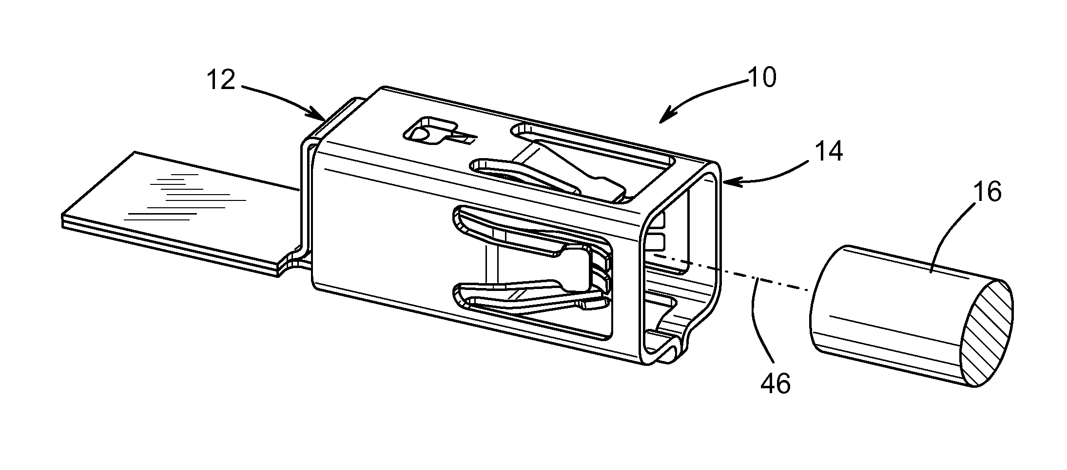
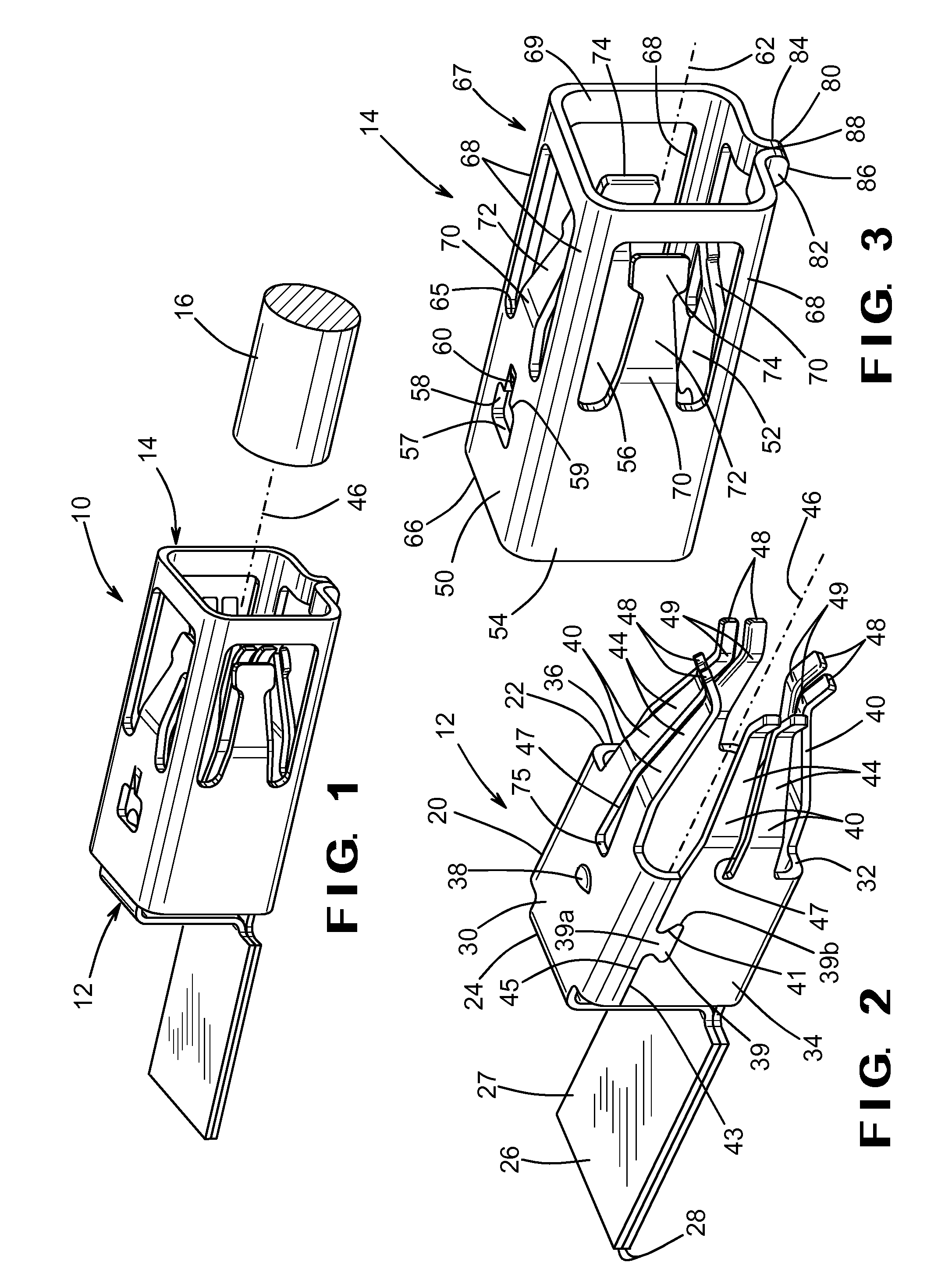
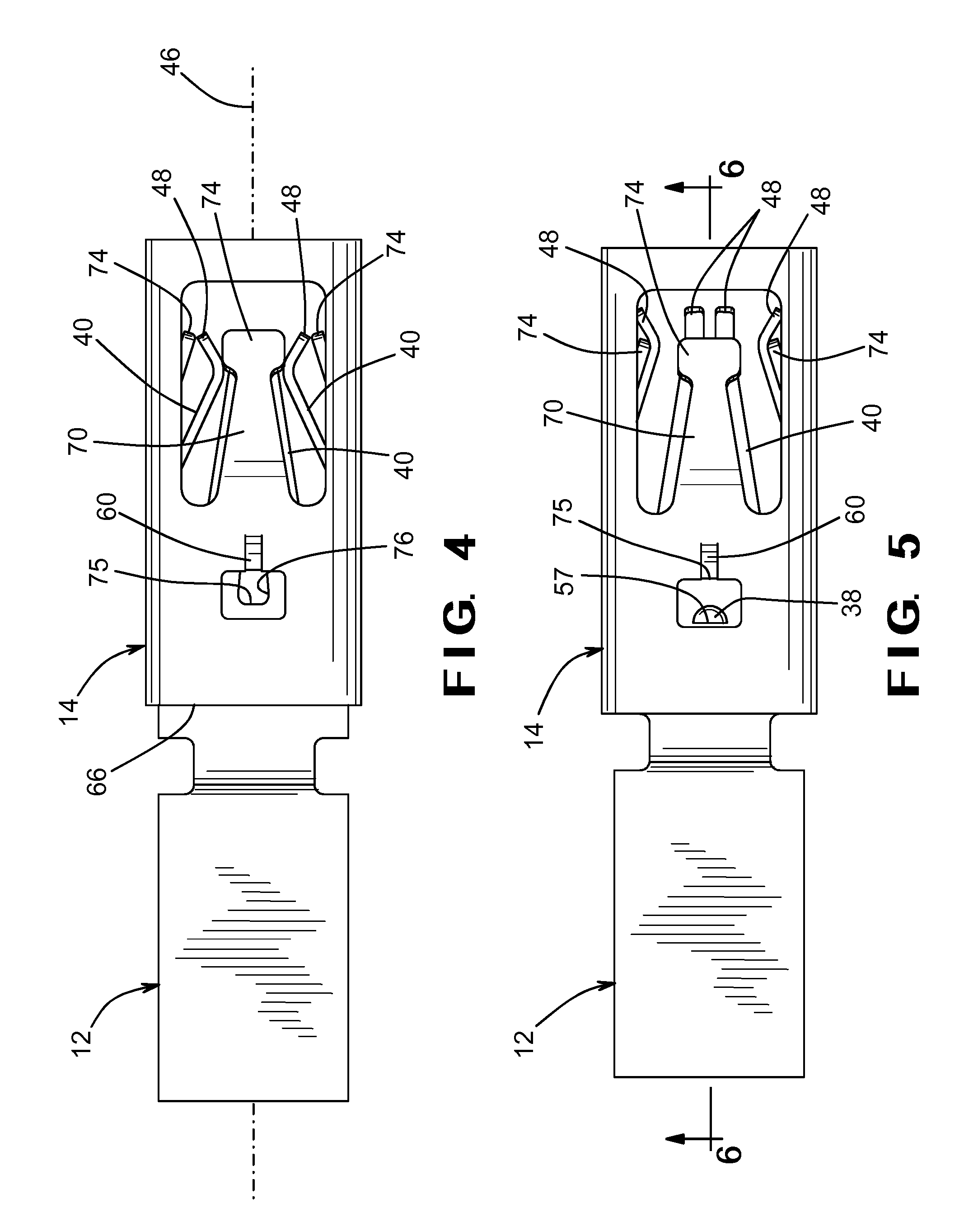
[0026]Referring now to the drawings, there is illustrated in FIG. 1 an electrical terminal assembly, indicated generally at 10. The electrical terminal assembly 10 includes a base, indicated generally at 12, and a spring member, indicated generally at 14. In an assembled condition of the electrical terminal assembly 10, the base 12 is inserted within the spring member 14, as shown in FIG. 1. In the embodiment shown, the electrical terminal assembly 10 has a rectangular or box-shape such that both the base 12 and the spring member 14 have four sides, as will be described below. The widths of the each of the sides may be equal or unequal. It should be understood that the base 12 and the spring member 14 may be shaped other than a four sided box, as shown in the figures. For example, the base 12 and the spring member 14 may have three sides, six sides, or any suitable number of sides. Alternatively, the base 12 and the spring member 14 may be cylindrical in shape. In a preferred embodi...


PUM

PropertyMeasurementUnit
axial movementaaaaaaaaaa
yield strengthaaaaaaaaaa
conductivityaaaaaaaaaa

Abstract

A method of assembling an electrical terminal having a base and a spring member. The base is provided with a plurality of base beams. The spring member is provided with a plurality of spring beams. The spring member defines an axis such that the plurality of spring beams is spaced radially apart from the axis. The spring beams deflected radially outwardly. The base is inserted in the spring member to position the base beams adjacent to the spring beams. The spring beams are released such that the spring beams retract radially inwardly against the base beams.

Description

CROSS-REFERENCE TO RELATED APPLICATIONS[0001]This application claims the benefit of U.S. Provisional Application No. 61 / 837,835, filed Jun. 21, 2013, and U.S. Provisional Application No. 61 / 864,155, filed Aug. 9, 2013, the disclosures of which are incorporated herein by reference.BACKGROUND OF THE INVENTION[0002]This invention relates in general to electrical terminals such as for use in high power vehicle electrical connectors. Electrical connectors commonly include a body having a nonconductive housing encasing a conductive set of female electrical terminals. The set of female terminals are each connected to a respective end of a wire connector or fuse element retained in the housing for completing an electrical circuit. The female terminals are inserted over a set of male blade terminals. For example, the male blade terminals may be housed in another connector housing, such as for example, a power distribution box. The female terminals are typically designed with a spring-type fe...

Claims


Application Information

Patent Timeline
Patent Type & Authority Applications(United States)
IPC IPC(8): H01R43/20
CPCH01R43/20H01R13/18H01R43/16H01R2201/26Y10T29/49217H01R13/11
Inventor GLICK, MICHAELPAVLOVIC, SLOBODANSADRAS-RAVINDRA, TULASI
Owner LEAR CORP
Features
  • R&D
  • Intellectual Property
  • Life Sciences
  • Materials
  • Tech Scout
  • Unparalleled Data Quality
  • Higher Quality Content
  • 60% Fewer Hallucinations
Learn More