
Pressurized Actuator

a technology of actuators and actuators, applied in the direction of pyrotechnical actuators, servomotors, weapons, etc., can solve the problems of increasing manufacturing costs, increasing shipping and handling costs, and exhibiting untenable moisture sensitivity of typical pyrotechnic compositions

Active Publication Date: 2015-03-19
JOYSON SAFETY SYST ACQUISITION LLC
View PDF6 Cites 11 Cited by
  • Summary
  • Abstract
  • Description
  • Claims
  • Application Information

AI Technical Summary

Benefits of technology

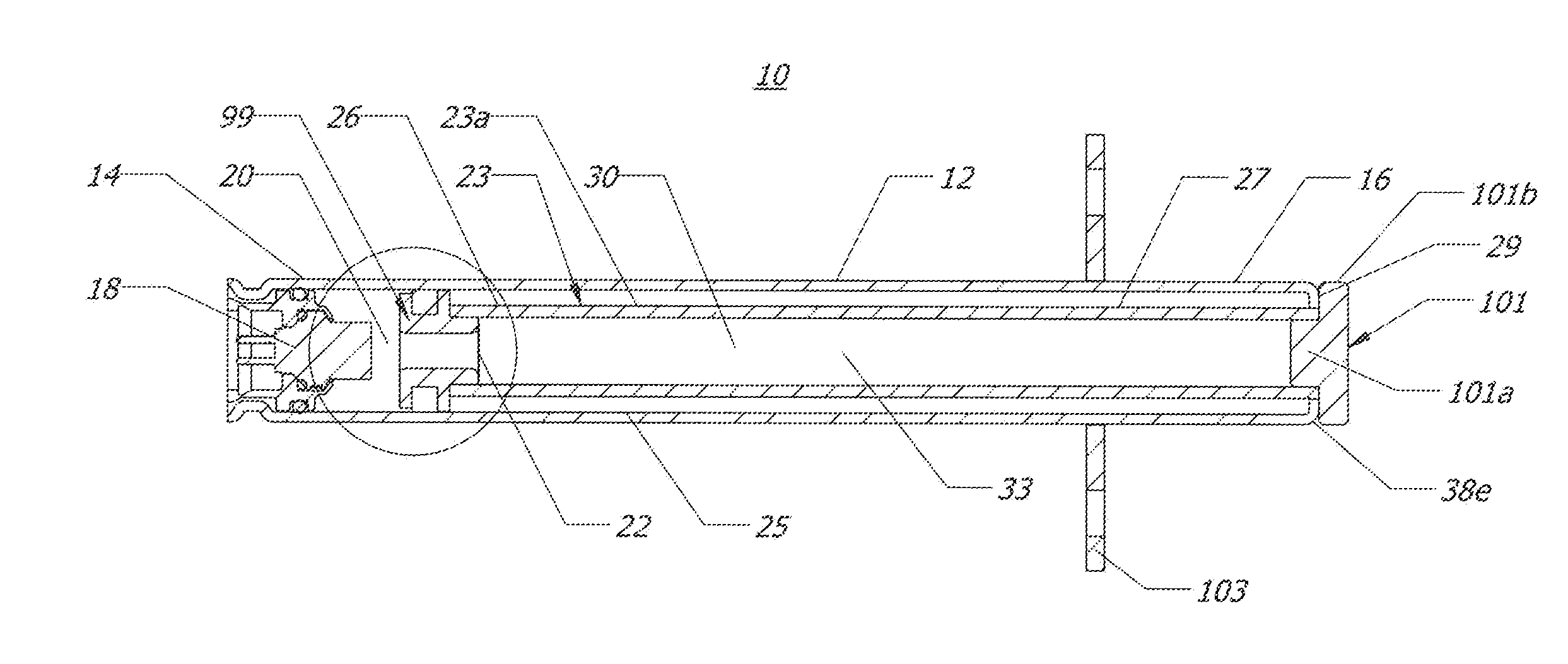
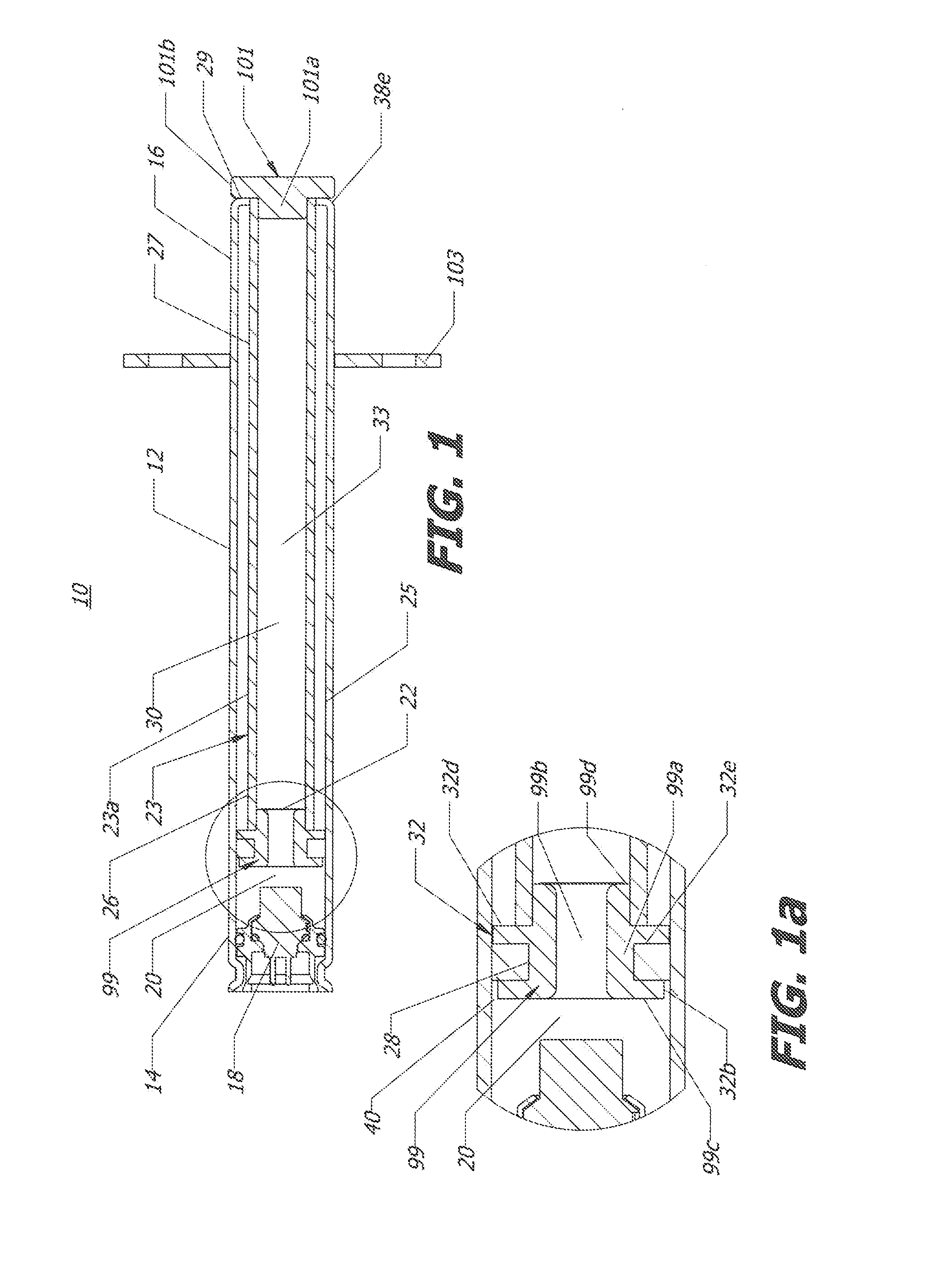
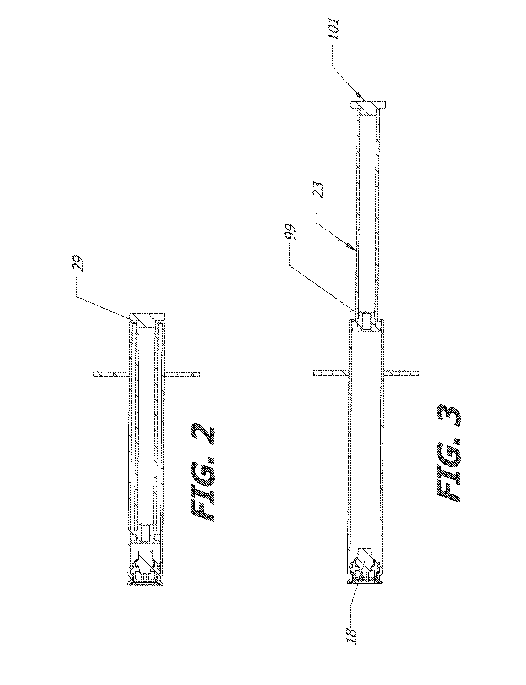
The present invention relates to a pyrotechnic actuator, which is a device used to create a controlled explosive force. The actuator includes a housing with a piston rod containing a sealed gas chamber filled with stored gas. The actuator also has an initiator that ruptures a seal on the piston rod to release the stored gas and propel the piston forward. The actuator has a flange on the piston rod that forms an annular conduit through which the gas can flow and drive the piston assembly through the housing. The technical effect of this invention is an actuator that provides a controlled explosive force with high reliability and efficiency.

Problems solved by technology

This increases the cost of manufacturing given that the gas generating composition must also be manufactured prior to insertion within the actuator.
Further, shipping and handling may be more complex or complicated due to transportation and related regulatory requirements.
Additionally, typical pyrotechnic compositions may exhibit untenable moisture sensitivity and increase the size of the actuator due to storage requirements within the actuator.

Method used


Image

  • Pressurized Actuator
  • Pressurized Actuator
  • Pressurized Actuator

Examples


Embodiment Construction

[0011]As shown in a first embodiment of FIG. 1, a linear actuator 10 contains a housing 12. The housing 12 contains a first end 14 and a second end 16. An initiator or igniter 18 is fixed within the first end 14 in a known manner, such as by a body bore seal for example. An ignition chamber 20 is formed proximate to the igniter 18. A burst shim or seal 22 may be fixed adjacent the chamber 20 thereby retaining the pressurized gas within the piston rod interior 30A tube or hollow piston rod 23 is contained within the housing 12 and extends from immediately adjacent the ignition chamber 20 to the second end 16 (prior to activation of the actuator). It will be appreciated that a portion 32 of a piston first end 26 may therefore have an outer diameter substantially equivalent to the inner diameter of the housing 12 as defined by the inner wall 25. An outer wall 23a of the piston 23 may be almost coextensive with the length of the housing 12. The portion or first piston, flange 32 of the ...


PUM

PropertyMeasurementUnit
surface areaaaaaaaaaaa
inner diameteraaaaaaaaaa
outer diameteraaaaaaaaaa

Abstract

A linear actuator contains a housing having a first end and a second end. A hollow piston is positioned within the housing to slidably engage with an inner wall of the housing. A sealed gas chamber is formed within the hollow piston and contains stored gas for driving the piston upon activation of the actuator.

Description

CROSS-REFERENCE TO RELATED APPLICATIONS[0001]This application claims the benefit of U.S. Provisional Application Ser. No. 61 / 864,955 filed on Aug. 12, 2013.TECHNICAL FIELD[0002]The present invention relates generally to gas generating systems, and to an improved linear actuator.BACKGROUND OF THE INVENTION[0003]The present invention relates to vehicle occupant protection systems or other safety systems employing linear actuators to elevate a vehicle surface such as a hood, in the event of collision or impact with a pedestrian. Known linear actuators typically employ pyrotechnic means to activate a piston within an actuator. This increases the cost of manufacturing given that the gas generating composition must also be manufactured prior to insertion within the actuator. Further, shipping and handling may be more complex or complicated due to transportation and related regulatory requirements. Additionally, typical pyrotechnic compositions may exhibit untenable moisture sensitivity an...

Claims


Application Information

Patent Timeline
Patent Type & Authority Applications(United States)
IPC IPC(8): C06D5/00
CPCC06D5/00F15B11/06F15B15/1457F15B15/19F15B15/1461
Inventor HENCK, JEREMY M.
Owner JOYSON SAFETY SYST ACQUISITION LLC
Learn More