Wireless communication node having neighbor node information registered

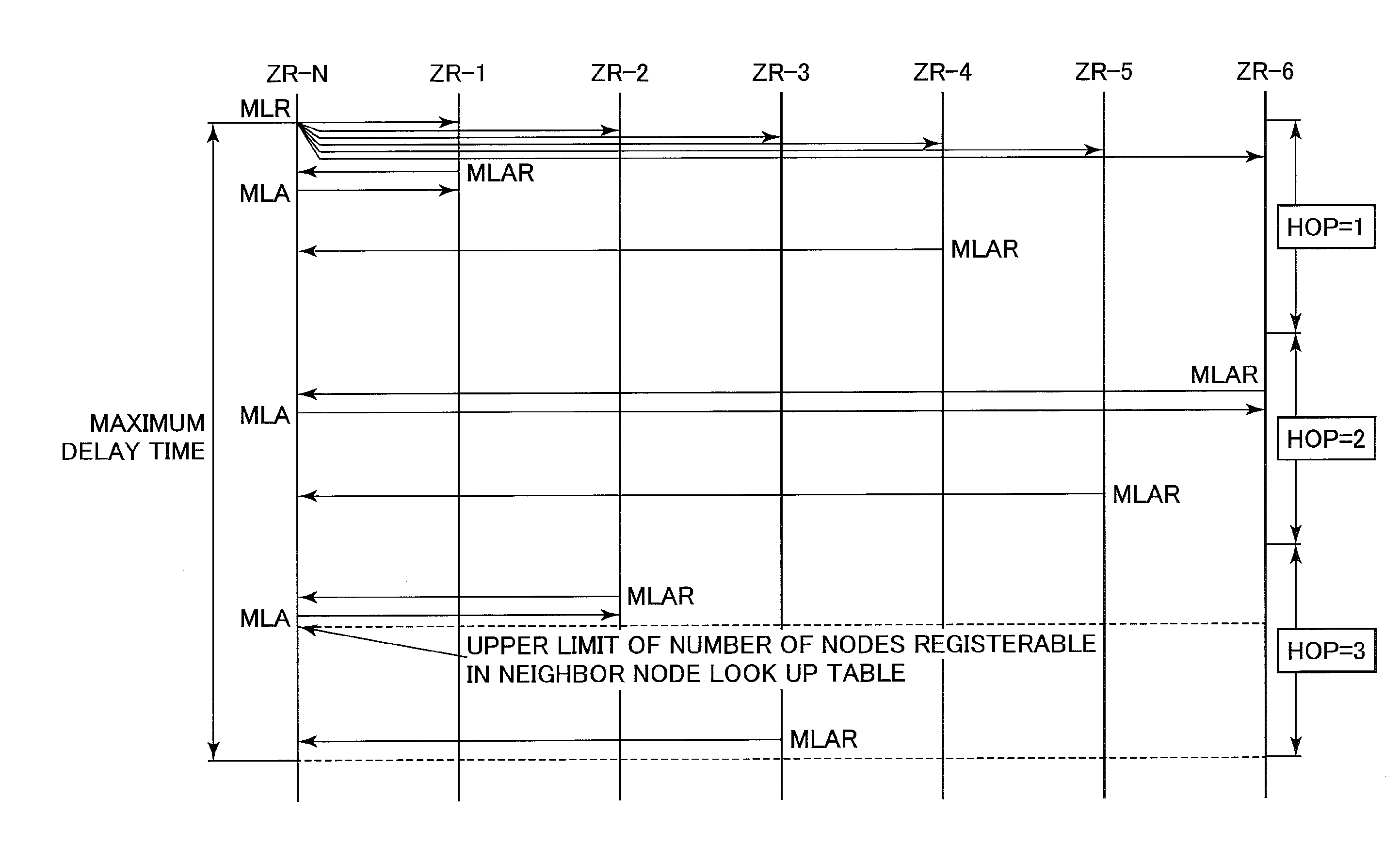
a wireless communication and neighbor node technology, applied in the field of wireless communication nodes, can solve the problems of not being able to register all neighbor nodes the newly installed relay node may not always be registered in the neighbor node lookup table, and the response to the mle link request (mlr) may not be appropriately received by the newly joined nod

Active Publication Date: 2015-03-26
OKI ELECTRIC IND CO LTD
View PDF6 Cites 29 Cited by
  • Summary
  • Abstract
  • Description
  • Claims
  • Application Information

AI Technical Summary

Benefits of technology

[0019]It is an object of the present invention to provide a wireless communication node which can register peripheral nodes suitable for neighbor nodes.
[0021]In accordance with the present invention, it is possible to register suitable peripheral nodes in a newly joining node for its neighbor nodes.

Problems solved by technology

That may cause the same IPv6 address to be generated within the network.
However, if the neighbor nodes send back their replies at once, the packets would collide with each other so that the replies to the MLE link request (MLR) may not appropriately be received by the newly joining node.
However, as described above, the timing of sending back MLE link accept and requests (MLARs) involves random factors, see FIG. 3 described later, and hence the conventional wireless communication nodes do not assure that a suitable node for a neighbor node can necessarily be selected, which satisfies requirements such as a small rank value in reaching the coordinator and a large Received Signal Strength Intensity (RSSI).
Furthermore, in the conventional method for creating a neighbor node lookup table, if the maximum number of register nodes registerable in a neighbor node lookup table is set fewer than neighbor nodes, it is impossible to register all the neighbor nodes in the neighbor node lookup table.
Therefore, even when the user intentionally installs a new relay node, the newly installed relay node may not always be registered in the neighbor node lookup table of the intended node.

Method used


Image

  • Wireless communication node having neighbor node information registered
  • Wireless communication node having neighbor node information registered
  • Wireless communication node having neighbor node information registered

Examples


Embodiment Construction

[0031]Now, preferred embodiments of the present invention will be described in detail with reference to the accompanying drawings. In the figures, the components and elements are merely schematically depicted to the extent that the present invention can be sufficiently understood. Therefore, the present invention is not to be restrictively comprehended only by the illustrated embodiments.

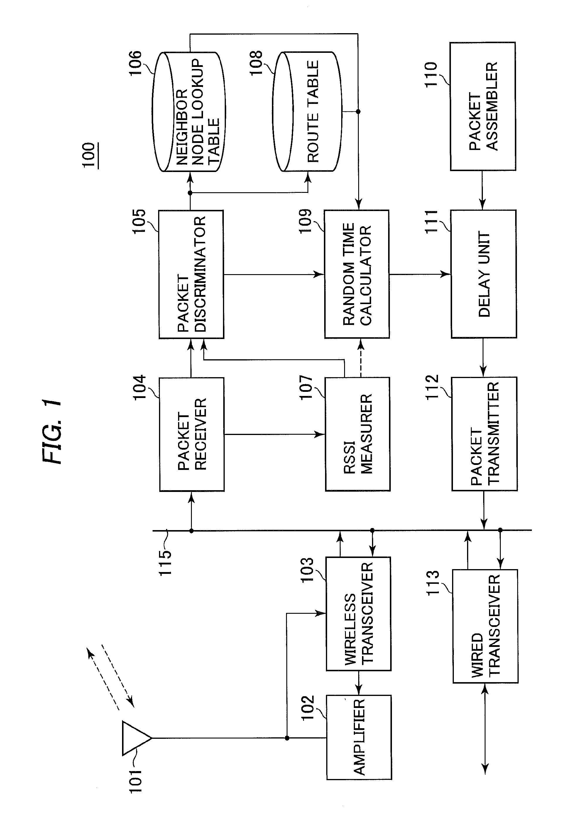
[0032]FIG. 1 is a schematic block diagram showing the configuration of a wireless communication node in a multi-hop wireless network in accordance with a preferred embodiment of the present invention. The multi-hop wireless network according to the embodiment may not be limited to nor out of spec of ZIP (ZigBee IP) requirements. For example, the multi-hop wireless network according to the illustrative embodiment may include wireless communication nodes according to the illustrative embodiment and a top node, the wireless communication nodes and top node corresponding to routers and a coordinator, re...


PUM


Abstract

A wireless communication node on the multi-hop wireless network has a control message exchanger for exchanging control messages with peripheral nodes to determine neighbor nodes whose information should be registered in a neighbor node information storage; a timing adjuster for adjusting, depending on a connective state of the wireless communication node in the network, a timing at which a first control message is sent back in response to a second control message arriving from other wireless communication nodes; and a registered node determiner for primarily referencing the order of arrival of a first control message from the other wireless communication node to determining neighbor nodes whose information should be registered in the neighbor node information storage.

Description

BACKGROUND OF THE INVENTION[0001]1. Field of the Invention[0002]The present invention relates to a wireless communication node, and more particularly to a wireless communication node having neighbor node information registered in a neighbor node lookup table in order to perform communications with a neighbor node on a multi-hop wireless network.[0003]2. Description of the Background Art[0004]A multi-hop wireless network is constituted with a plurality of wireless communication nodes, each of which has a packet transfer function to transfer and receive packets to and from its adjacent wireless communication nodes to thereby allow packets to be transmitted even to nodes residing beyond the area covered by the radio waves emitted by that node. A representative example of such a multi-hop wireless network is ZigBee (trade name) IP (Internet Protocol) technology as described in, for example, “Method B” of TTC standards “JJ-300, 10 ECHONET Lite-directed Home Network Communication Interfac...

Claims


Application Information

Patent Timeline
Patent Type & Authority Applications(United States)
IPC IPC(8): H04W36/00H04W60/00H04L45/122
CPCH04W60/00H04W36/0061H04W40/00
Inventor NOZAKI, MASANORINAKANO, YOSHIHISAHASHIZUME, TAKAHIKO
Owner OKI ELECTRIC IND CO LTD
Why Eureka
Try Eureka