Supercharge Your Innovation With Domain-Expert AI Agents!

Pyrotechnic Actuator

a technology of pyrotechnic actuators and actuators, which is applied in the direction of pyrotechnic actuators, pedestrian/occupant safety arrangements, vehicle components, etc., can solve problems such as weak areas

Active Publication Date: 2015-04-02
JOYSON SAFETY SYST ACQUISITION LLC
View PDF3 Cites 5 Cited by
  • Summary
  • Abstract
  • Description
  • Claims
  • Application Information

AI Technical Summary

Benefits of technology

This patent describes an actuator that helps control the movement of a piston rod. The actuator has a housing and a piston rod assembly. A first piston end cap is fixed at the end of the piston rod, and a second piston end cap is fixed at the other end. The first piston end cap has a larger outer diameter than a second piston end cap, and a plenum is formed between the second piston end cap and the piston rod inner wall. The actuator also includes an energy management device, like a crushable sleeve or other deformable device, which is designed to absorb and manage the energy of the actuator. The actuator can be used in vehicles and other systems to control the movement of the piston rod.

Problems solved by technology

When assembling various constituents of typical pyrotechnic actuators together, stress risers caused by manufacturing processes such as crimping, welding, press-fitting, or any other suitable assembly process may be an area(s) of weakness when exposed to physical shock upon actuation of the actuator.

Method used


Image

  • Pyrotechnic Actuator
  • Pyrotechnic Actuator
  • Pyrotechnic Actuator

Examples


Embodiment Construction

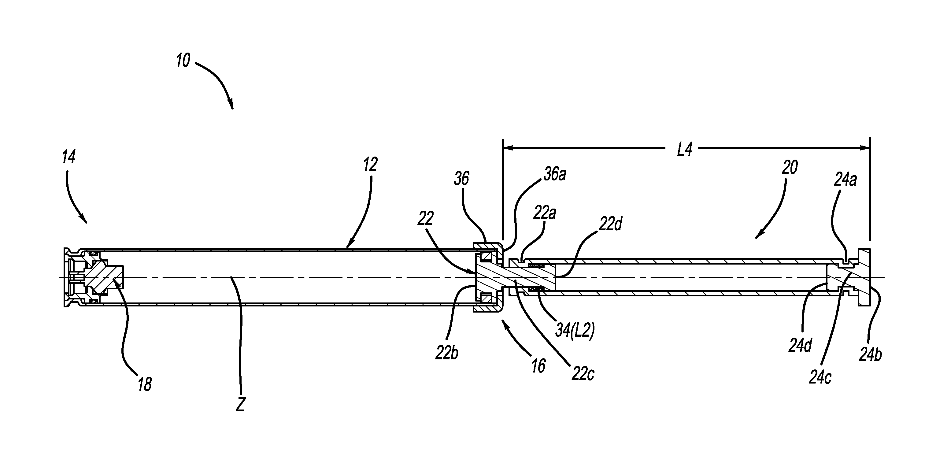
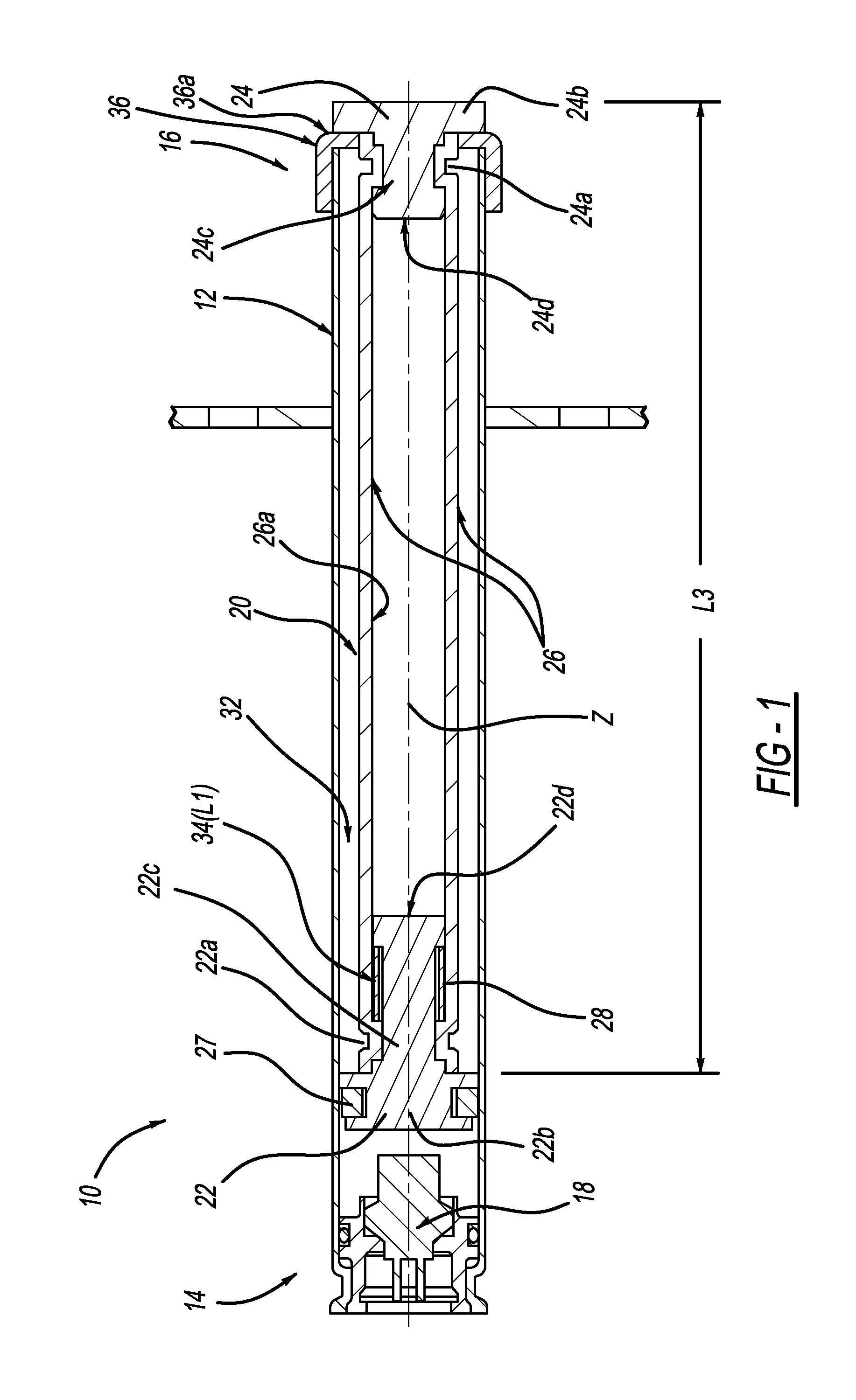
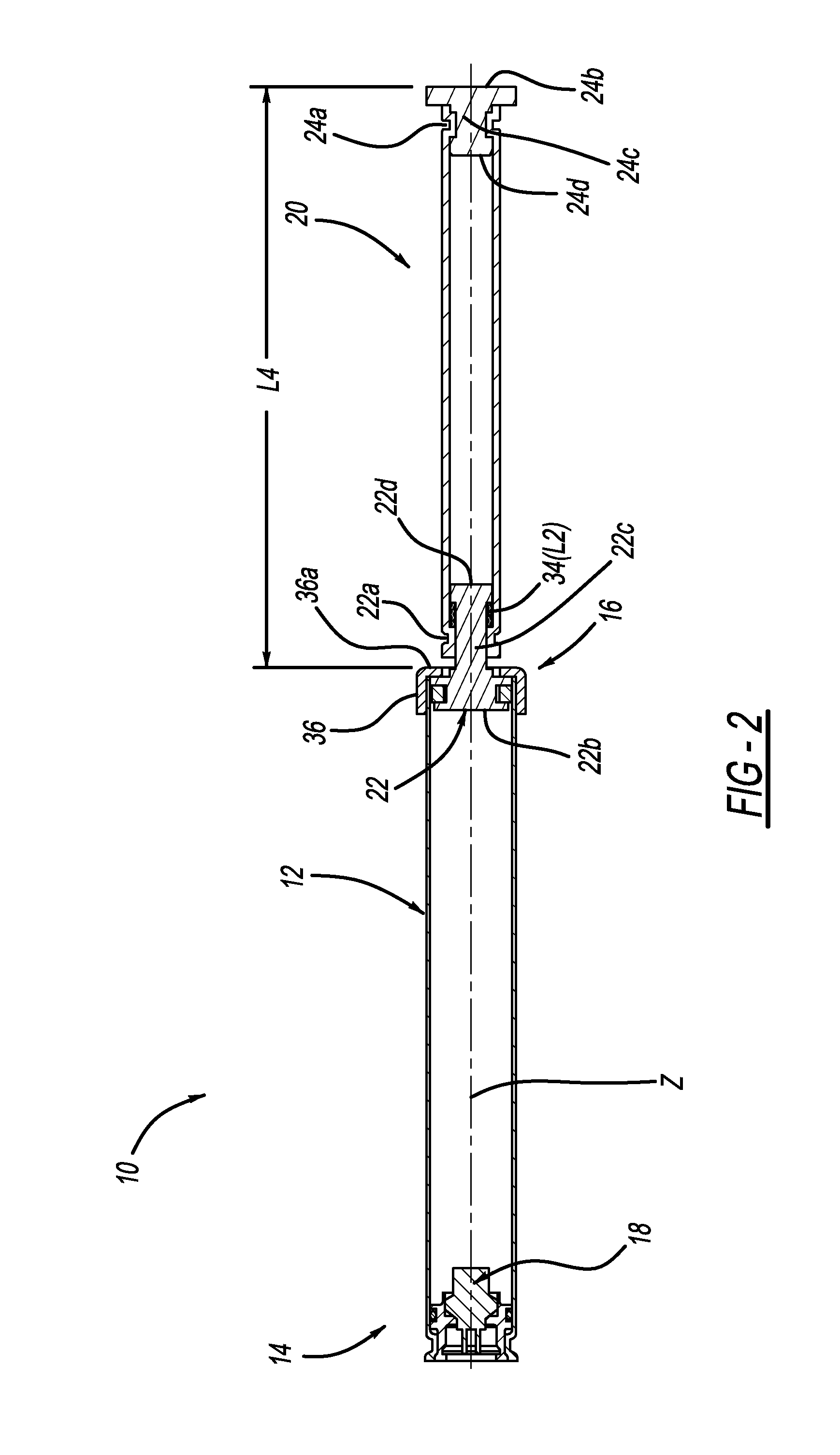
[0008]As shown in the Figures, a linear actuator 10 contains a housing 12. The housing 12 contains a first end 14 and a second end 16. An initiator or igniter 18 is fitted within the first end 14 and seals the first end 14 in a known manner. A piston or piston rod assembly 20 is positioned adjacent the igniter 18 prior to actuation of the actuator 10, wherein the piston 20 contains a first end 22 and a second end 24. A piston rod 26 connects the first piston end 22 with the second piston end 24. As shown in the figures, a first crimp 22a fixes the piston rod 26 to piston end 22. As indicated above, the first crimp 22a exemplifies any similar stress riser caused by manufacturing process such as welding, crimping, press-fitting and so forth. As shown in the drawings, the piston end 22 has a first portion 22b (proximate to the igniter 18) having a relatively wider diameter, and a third opposite portion 22d having a relatively smaller diameter. A second or intermediate portion 22c of pi...


PUM


Abstract

A novel actuator contains a housing having a first end, a second end, and an inner wall. A piston rod assembly is contained within the housing, wherein the assembly contains a piston rod, a first end cap fixed at one end of the piston rod, and a second end cap fixed at an opposing end of the piston rod. An energy management device is constrained about an outer diameter of the first end cap, wherein upon actuation of the actuator, the energy management device may under predetermined conditions be deformed upon movement of said piston rod.

Description

CROSS-REFERENCE TO RELATED APPLICATIONS[0001]This application claims the benefit of U.S. Provisional Application Ser. No. 61 / 884,967 filed on Sep. 30, 2013.TECHNICAL FIELD[0002]The present invention relates generally to an improved linear actuator that may be used to elevate an automotive hood or bonnet upon a pedestrian impact with the front of the vehicle.BACKGROUND OF THE INVENTION[0003]The present invention relates to vehicle occupant protection systems or other safety systems employing linear actuators to elevate a vehicle surface such as a hood, in the event of collision or impact with a pedestrian. Exemplary linear actuators typically employ pyrotechnic means to activate a piston within an actuator. With regard to certain events, such as a bonfire event, or with regard to bonfire testing or mounted dry fire testing, the energy created at that time must be managed. Stated another way, in certain environments, pyrotechnic actuators may be activated under “no-load” conditions wh...

Claims


Application Information

Patent Timeline
IPC IPC(8): B60R21/38F15B15/26F15B15/19
CPCB60R21/38F15B15/26F15B15/19F15B15/1457F15B15/22F15B15/148
Inventor HENCK, JEREMY M.
Owner JOYSON SAFETY SYST ACQUISITION LLC
Features
  • R&D
  • Intellectual Property
  • Life Sciences
  • Materials
  • Tech Scout
  • Unparalleled Data Quality
  • Higher Quality Content
  • 60% Fewer Hallucinations
Learn More