
Distributed Optical Switching Architecture for Data Center Networking

a technology of optical switching and data center networking, applied in the field of data communication, can solve the problems of unresolvable cabling issues, unavoidable burden of data center construction and maintenance costs, and increased complexity of hierarchy architecture,

Inactive Publication Date: 2015-04-09
COADNA PHOTONICS
View PDF4 Cites 73 Cited by
  • Summary
  • Abstract
  • Description
  • Claims
  • Application Information

AI Technical Summary

Benefits of technology

This patent describes a system that has two racks of servers and switches. The system uses optical switches to connect the servers in each rack. The first optical switch connects to the first rack, the second optical switch connects to the second rack, and the first optical switch also connects to the second optical switch. This allows for faster data transfer and better performance between the two sets of servers. The technical effect is a more efficient and reliable communication network within the system.

Problems solved by technology

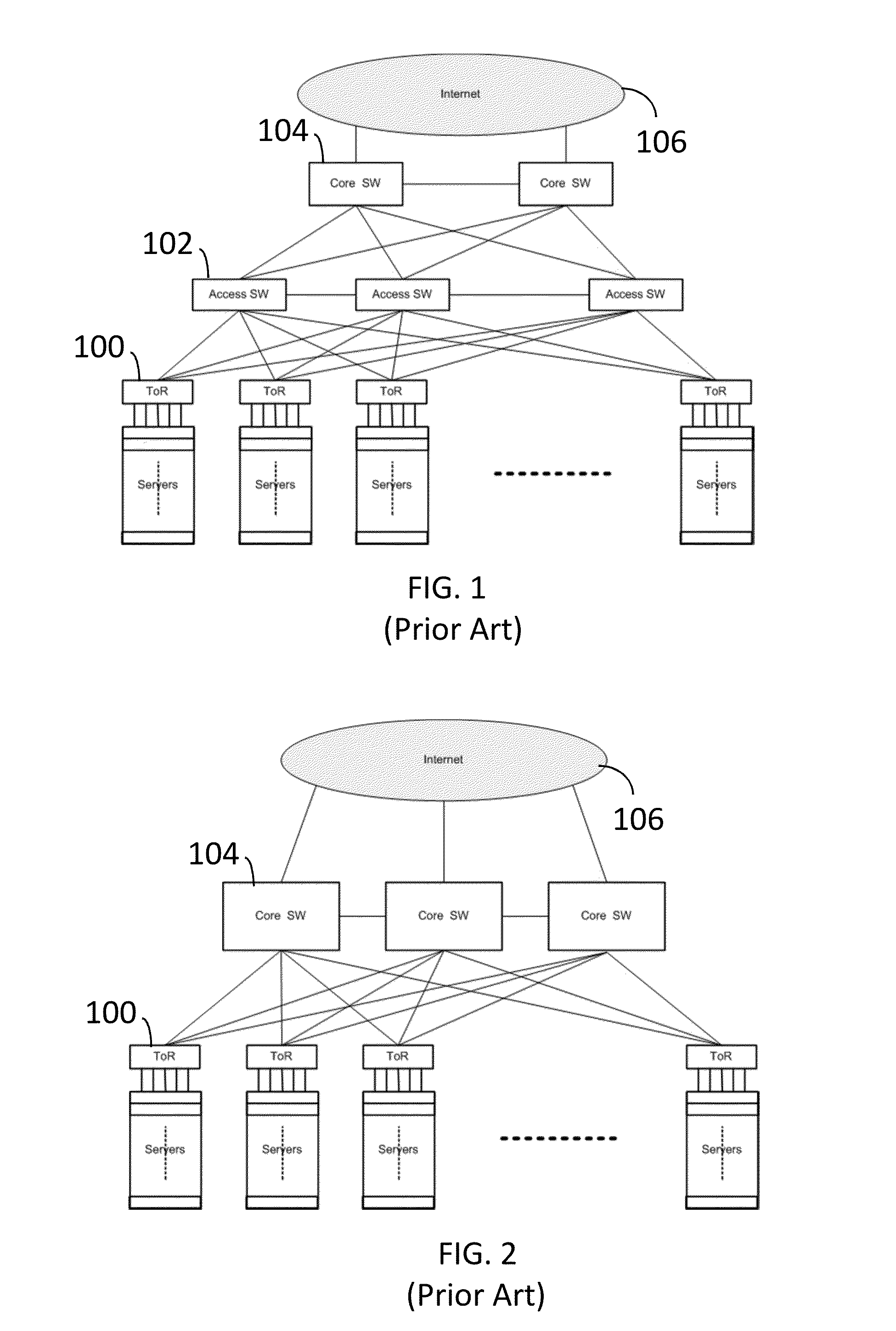
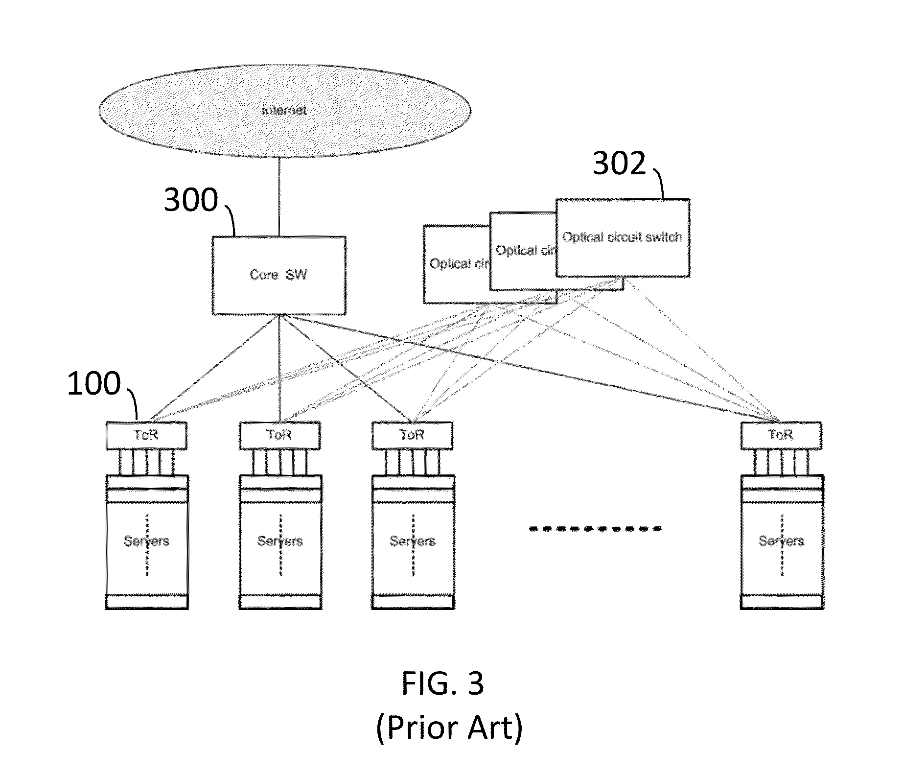
This hierarchical architecture suffers from increasing complexity, particularly as the data center scales.
For example, cabling becomes an un-resolvable issue as the number of links increases along with the number of hierarchical layers and server numbers.
Nevertheless, long-distance cabling is inevitable and becomes an unavoidable burden associated with data center construction and maintenance costs.
Furthermore, electrical switches usually consume tens of watts per switch port.
Still, fundamental problems remain.

Method used


Image

  • Distributed Optical Switching Architecture for Data Center Networking
  • Distributed Optical Switching Architecture for Data Center Networking
  • Distributed Optical Switching Architecture for Data Center Networking

Examples


Embodiment Construction

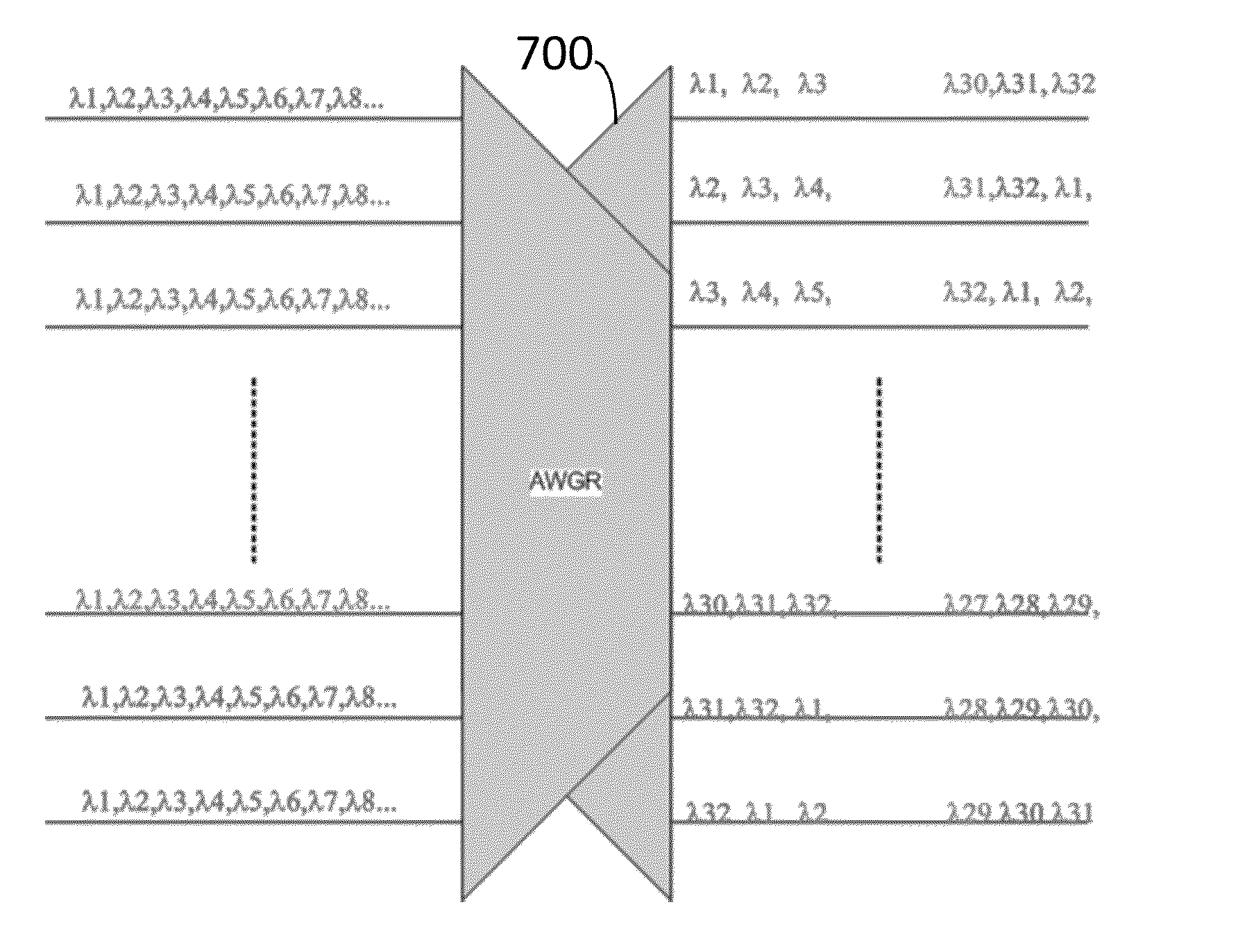
[0028]A multiple dimension and high radix optical distributed switching network architecture for internal data center interconnections is disclosed. The link capacity in this distributed switching network is also optically reconfigurable to be adaptive to the dynamic pattern of internal data center traffic. The solution is naturally scalable to support thousands of servers (e.g., Tiers 3&4 data centers) to millions of servers (e.g., Tier 1 data centers).

[0029]FIG. 5 depicts an N by M server rack arrays in a data center. Each server rack 500 contains dozens of servers and also contains a top of rack (TOR) electrical switch 502. TOR switches 502 aggregate the traffic from each server and generate a flow table for inter-server rack traffic. A layer of optical wavelength switching nodes 504 are introduced above each TOR switch. A TOR switch connects to optical wavelength switching nodes with a number of Dense Wavelength Division Multiplexing (DWDM) signals. Optical wavelength switching ...


PUM


Abstract

A system has a first rack with a first set of servers and a first top of rack switch and a second rack with a second set of servers and a second top of rack switch. A first optical switch is connected to the first top of rack switch. A second optical switch is connected to the second top of rack switch and the first optical switch. The first optical switch and the second optical switch each employ wavelength selective switching.

Description

CROSS-REFERENCE TO RELATED APPLICATION[0001]This application claims priority to U.S. Provisional Patent Application Ser. No. 61 / 886,553, filed Oct. 3, 2013, the contents of which are incorporated herein by reference.FIELD OF THE INVENTION[0002]This invention relates generally to data communications. More particularly, this invention relates to a distributed optical switching architecture for data center networking.BACKGROUND OF THE INVENTION[0003]“Big data” is prevalent. There is exponentially increasing computing and storage needs for big data. Cloud architectures are commonly used to address big data challenges. In a data center, server and storage resources are interconnected with packet switches and routers which provide the basic internal data center networking functionality. Data centers are also interconnected across wide area networks through routing and transport systems known as the cloud.[0004]Data centers can be of three types: private, public or virtually private. The s...

Claims


Application Information

Patent Timeline
IPC IPC(8): H04Q11/00
CPCH04Q11/0005H04Q2011/0016H04Q2011/0052H04Q2011/0009H04Q2011/0015H04Q2011/0032H04Q2011/006
Inventor ZHU, ZHONGHUAZHONG, SHAN
Owner COADNA PHOTONICS
Learn More