

Illumination apparatus and display unit
a technology of illumination apparatus and display unit, which is applied in the direction of lighting and heating apparatus, instruments, non-linear optics, etc., can solve the problems of partially modulating the light intensity of the light source, the difficulty of the edge light method, etc., and achieve the effect of a moderate change in the plane of luminance distribution
- Summary
- Abstract
- Description
- Claims
- Application Information
AI Technical Summary
Benefits of technology
Problems solved by technology
Method used
Image

Examples
first embodiment
2. Modification of First Embodiment
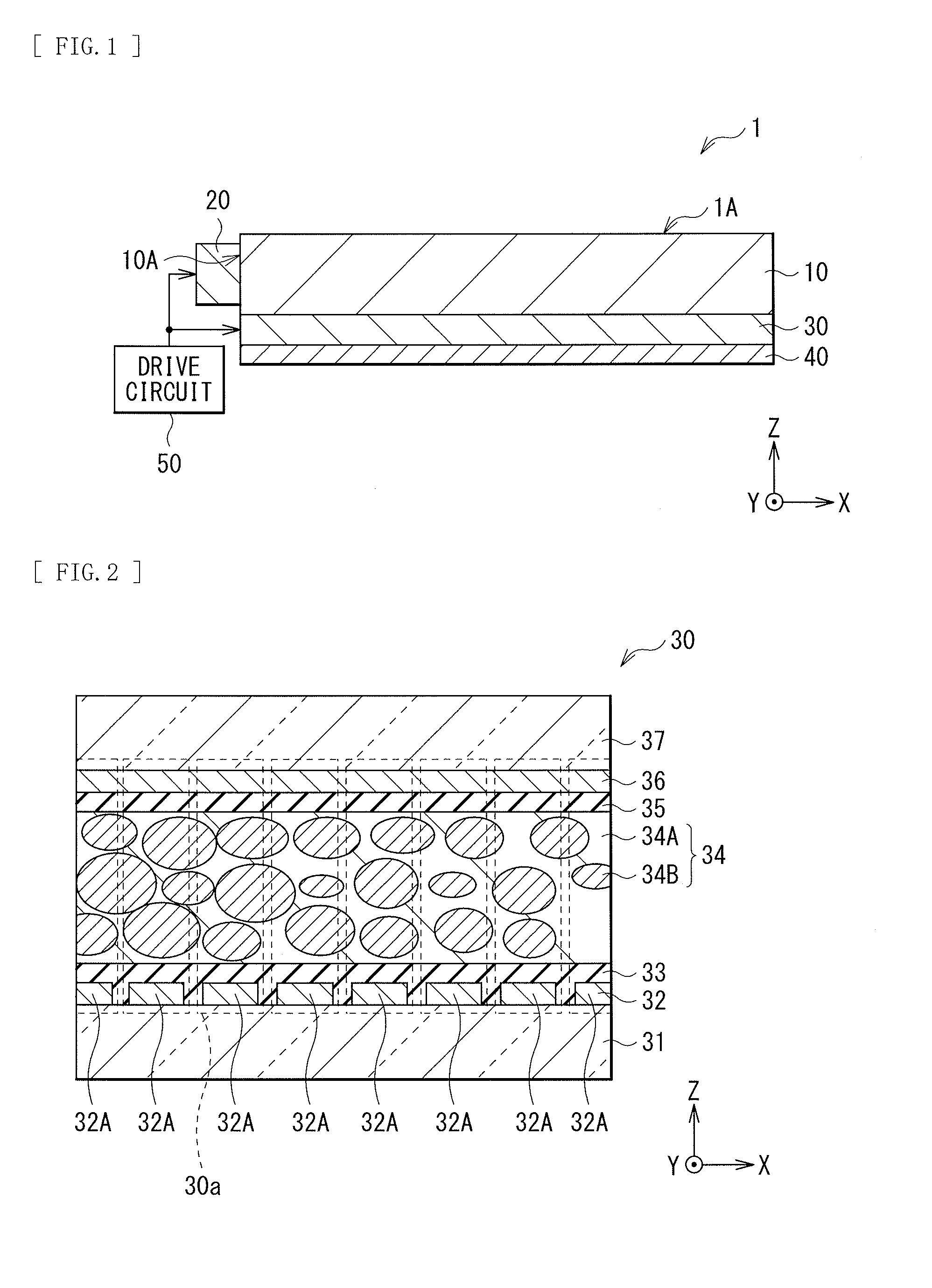
[0168]In the above-described embodiment, the streaky structure, the porous structure, or the rod-like structure of the bulk 34A has the long axis in the direction parallel to or substantially parallel to the light incident surface 10A; however, for example, may have the long axis in a direction orthogonal to or substantially orthogonal to the light incident surface 10A. At this time, the alignment films 33 and 35 have alignment direction that is a direction orthogonal to or substantially orthogonal to the light incident surface 10A.
[0169]FIG. 23 schematically illustrates an example of alignment state in the bulk 34A and the microparticle 34B during no-voltage application. FIG. 24 schematically illustrates an alignment state in the bulk 34A and the microparticle 34B during voltage application.
[0170]For example, as illustrated in FIG. 23, the bulk 34A and the microparticle 34B may have a configuration in which the direction of the optical axis AX1 of...
second embodiment
2. Second Embodiment
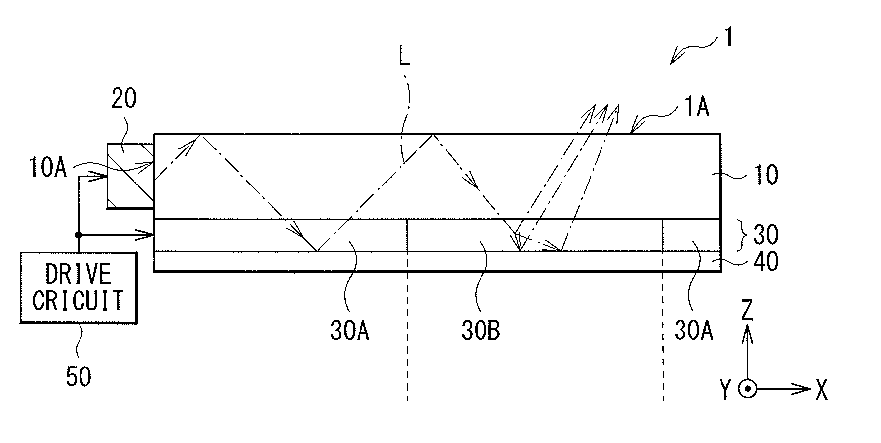
[0177]FIG. 25 is a sectional diagram illustrating an example of a schematic configuration of an illumination apparatus 2 according to a second embodiment of the technology. The illumination apparatus 2 in the present embodiment is different from the configuration of the illumination apparatus 1 according to the above-described first embodiment in that a light modulation device 60 is provided in place of the light modulation device 30. Therefore, in the following description, differences with the above-described embodiment will be described mainly, and description for common points to the above-described embodiment will be arbitrarily omitted.
[0178]For example, the light modulation device 60 may be tightly adhered to the back (the lower surface) of the light guide plate 10 without an air layer in between, and may be adhered to the back of the light guide plate 10 with, for example, an adhesive agent (not illustrated) in between. For example, as illustrated in FIG....
modification 1
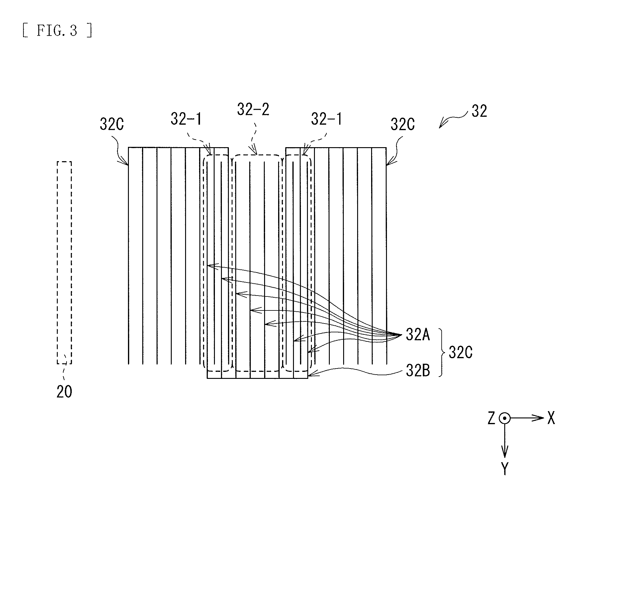
[0202]In the above-described embodiments, the upper electrode 36 may be configured to include the similar configuration to the plurality of electrode blocks 32C, instead of the lower electrode 32.
[0203]FIG. 29 illustrates an example of a planar configuration of the upper electrode 36. (A) and (B) of FIG. 30 each illustrate another example of the planar configuration of the upper electrode 36. The upper electrode 36 is provided on the surface of the transparent substrate 37 (specifically, on a surface of the transparent substrate 37 opposing to the transparent substrate 31), and is configured to include the plurality of partial electrodes 36A. The plurality of partial electrodes 36A each extend in one direction (the first direction) in plane, and are arranged in a direction intersecting the first direction. For example, the first direction may be a direction parallel to or substantially parallel to the light incident surface 10A. Note that the first direction may be a direction obliq...
PUM
| Property | Measurement | Unit |
|---|---|---|
| Time | aaaaa | aaaaa |
| Electric potential / voltage | aaaaa | aaaaa |
| Width | aaaaa | aaaaa |
Abstract
Description
Claims
Application Information