Image-forming apparatus
a technology of image-forming apparatus and coil, which is applied in the direction of electrographic process apparatus, instruments, optics, etc., can solve the problems of humming noise and coil humming noise, and achieve the effect of ensuring the responsiveness of heater control during printing and suppressing coil humming nois
- Summary
- Abstract
- Description
- Claims
- Application Information
AI Technical Summary
Benefits of technology
Problems solved by technology
Method used
Image

Examples
first embodiment
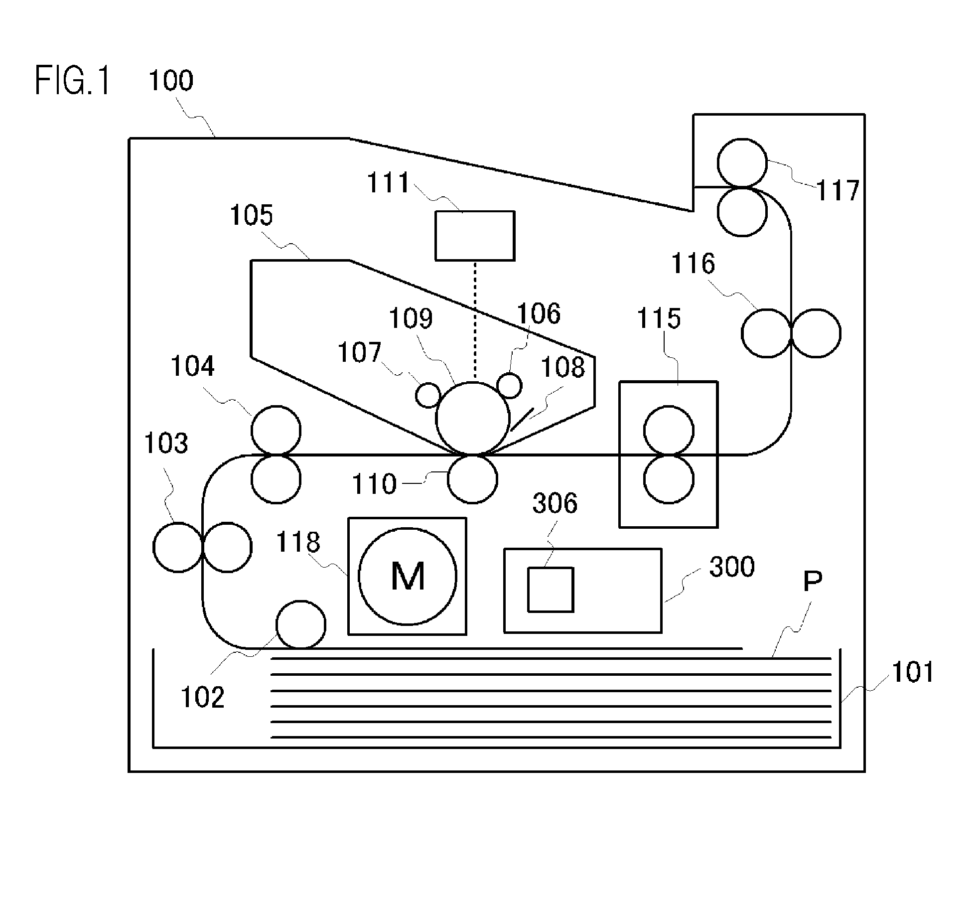
[0040]FIG. 1 shows an overview of the composition of an image-forming apparatus 100 relating to an embodiment of the present invention. A recording material (hereinafter called “recording paper P”) loaded in a paper supply cassette 101 is conveyed to a process cartridge 105 at a prescribed timing, via a pick-up roller 102, a paper feed roller 103 and a paper stop roller 104. The process cartridge 105 is composed in an integrated fashion by a charging means 106, a developing means 107, a cleaning means 108 and a photosensitive drum 109. In the process cartridge 105, a series of steps of an electrophotographic process, which is a commonly known technique, are carried out by laser light emitted from the exposure light means 111, and an unfixed toner image is thereby formed on the photosensitive drum 109. When the unfixed toner image on the photosensitive drum 109 is transferred to the recording paper P by a transferring means 110, the recording paper P is subjected to a heating and pre...
second embodiment
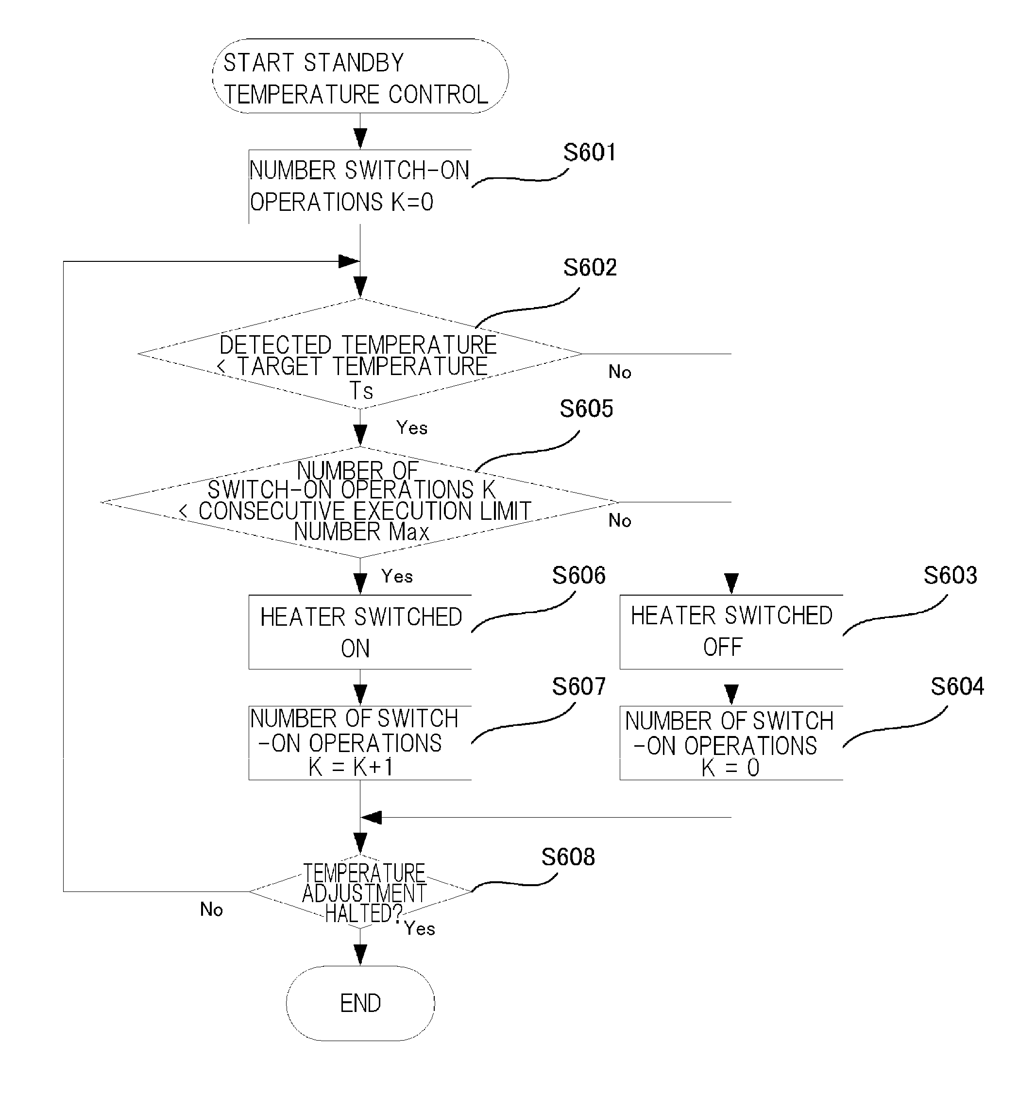
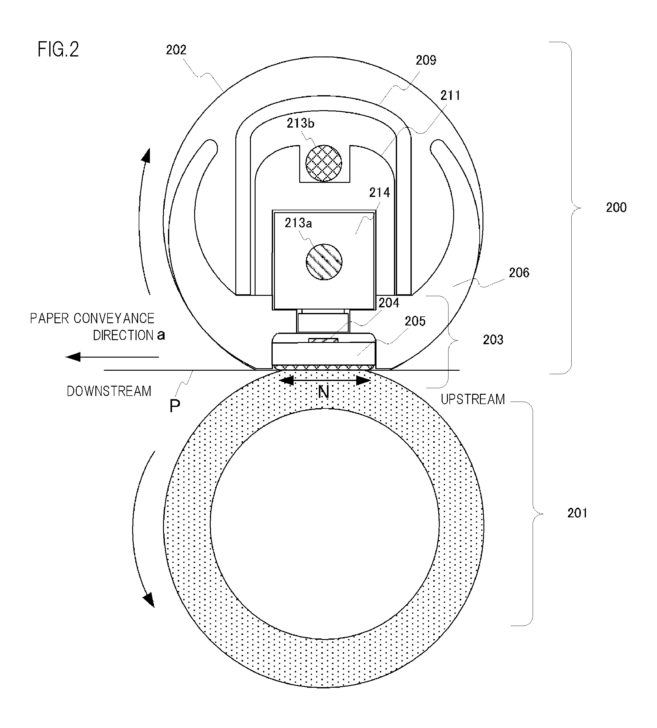
[0066]An image-forming apparatus relating to a second embodiment of the present invention is now described with reference to FIG. 8 to FIG. 12. The present embodiment describes desirable conditions of one control cycle for satisfying flicker standards in wave number control during standby. The composition of the fixing apparatus 115 and the composition of the ceramic heater drive circuit (reference numerals) are the same as in the first embodiment, and therefore further description thereof is omitted here.
[0067]According to the international standard IEC / EN 61000-3-3, the upper limit value of the Plt value is designated as 0.65. Furthermore, since the flicker depends greatly on the sensitivity of the viewer's eyes, this also depends on individual differences, the differences between lamps, fluorescent lights and other appliances, and environmental differences. Consequently, it is necessary to set one control cycle by taking account of the flicker specifications described above and v...
third embodiment
[0083]Table 1 indicated below is one example showing a relationship between the number of consecutive switch-on operations of the heater, and the Pit value which is a numerical value giving a quantitative representation of the long-term flicker, in a case where power is supplied by the waveform shown in FIG. 5B. For example, if the number of consecutive switch-on operations of the heater is two, then the Plt value is 0.429 if the waveform in FIG. 5B is supplied consecutively in two control cycles.
TABLE 1Heater switch-onconsecutive numberPlt value30.43320.42910.407
[0084]The Plt value varies with the conditions such as the input power ratio to the ceramic heater 203, the resistance value of the heat generating resistance 204, the commercial AC voltage, the commercial AC frequency, and so on, and the smaller the value, the better the situation. In general, greater voltage fluctuation per unit time is generated, the higher the commercial AC voltage value or the commercial AC frequency, ...
PUM
 Abstract
Description
Claims
Application Information
 - R&D Engineer
- R&D Manager
- IP Professional
- Industry Leading Data Capabilities
- Powerful AI technology
- Patent DNA Extraction
Browse by: Latest US Patents, China's latest patents, Technical Efficacy Thesaurus, Application Domain, Technology Topic.
© 2024 PatSnap. All rights reserved.Legal|Privacy policy|Modern Slavery Act Transparency Statement|Sitemap