
Assembly of an electrical connector and a cable unit and electronic device including the assembly

a technology of electrical connectors and cables, applied in the direction of two-part coupling devices, coupling devices effected by permanent deformation, connection, etc., can solve the problems of time-wasting and relatively complicated assembly procedures, and achieve the effect of enhancing assembly convenience and reducing assembly tim

Active Publication Date: 2015-04-30
WISTRON CORP
View PDF5 Cites 4 Cited by
  • Summary
  • Abstract
  • Description
  • Claims
  • Application Information

AI Technical Summary

Benefits of technology

The patent text describes an assembly of an electrical connector and cable unit that allows for easy assembly and reduced assembly time. The connector has conductive terminals that make electrical connections to cables through adapter terminals. The adapter terminals are connected to the cables' core wire, and each conductive terminal is connected to multiple cables through its corresponding adapter terminal. The assembly allows for convenient and efficient connection between electrical devices.

Problems solved by technology

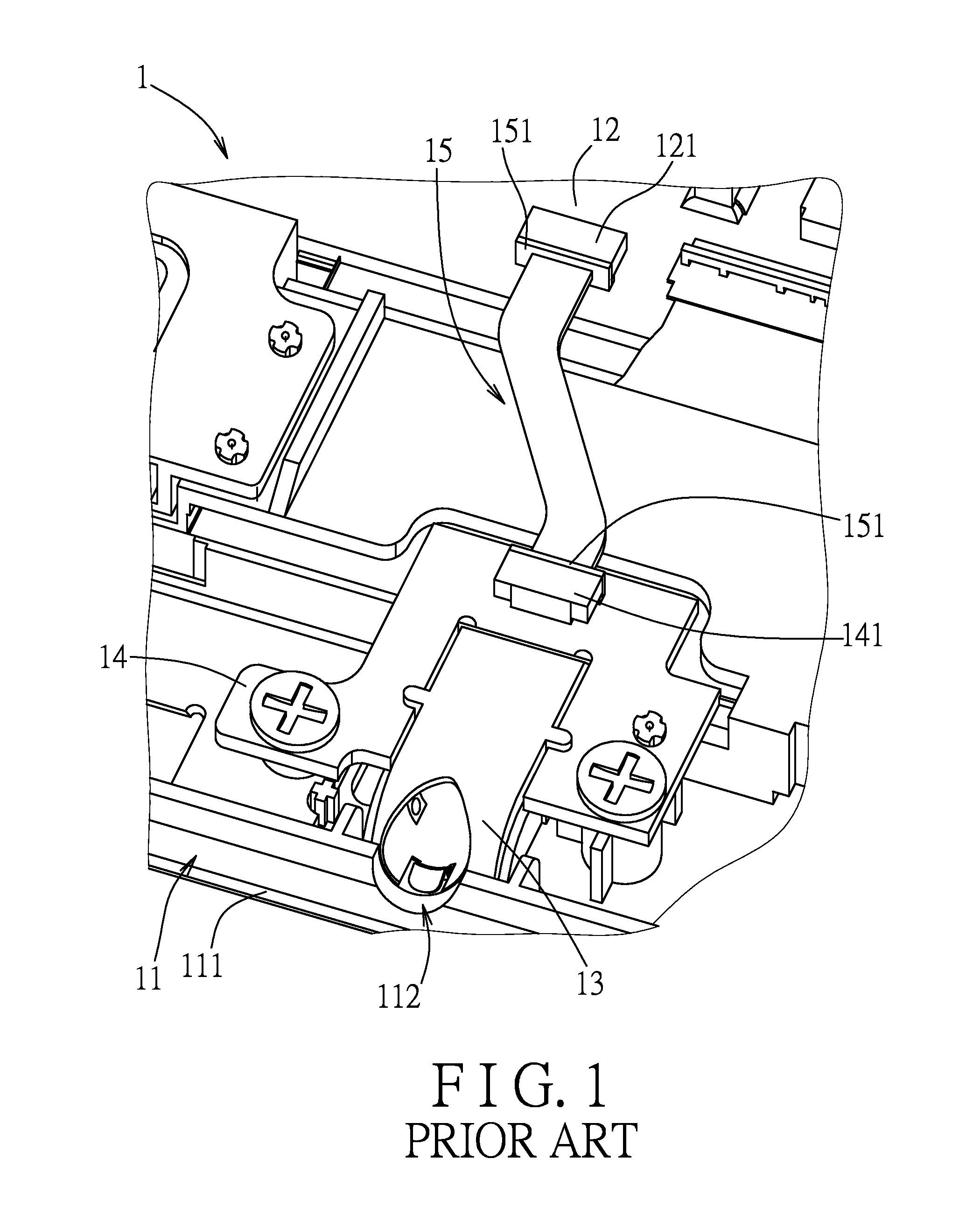
Since the conductive terminals of the audio connector 13 have to be soldered onto the circuit board 14 so as to electrically connect the audio connector 13 to the mother board 12 through the circuit board 14 and the cable unit 15, the assembling procedure is relatively complicated and time-wasting.

Method used


Image

  • Assembly of an electrical connector and a cable unit and electronic device including the assembly
  • Assembly of an electrical connector and a cable unit and electronic device including the assembly
  • Assembly of an electrical connector and a cable unit and electronic device including the assembly

Examples


first embodiment

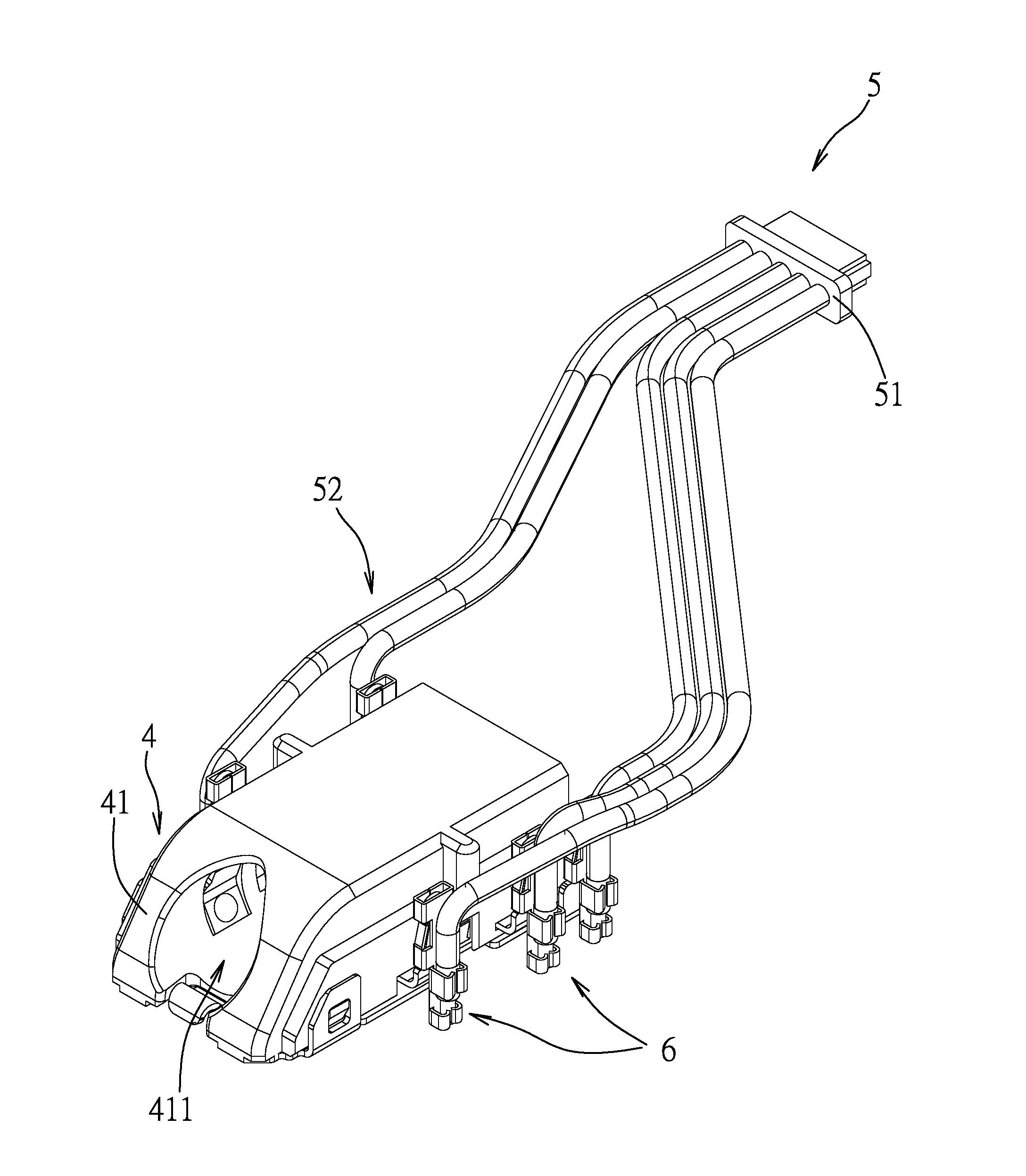
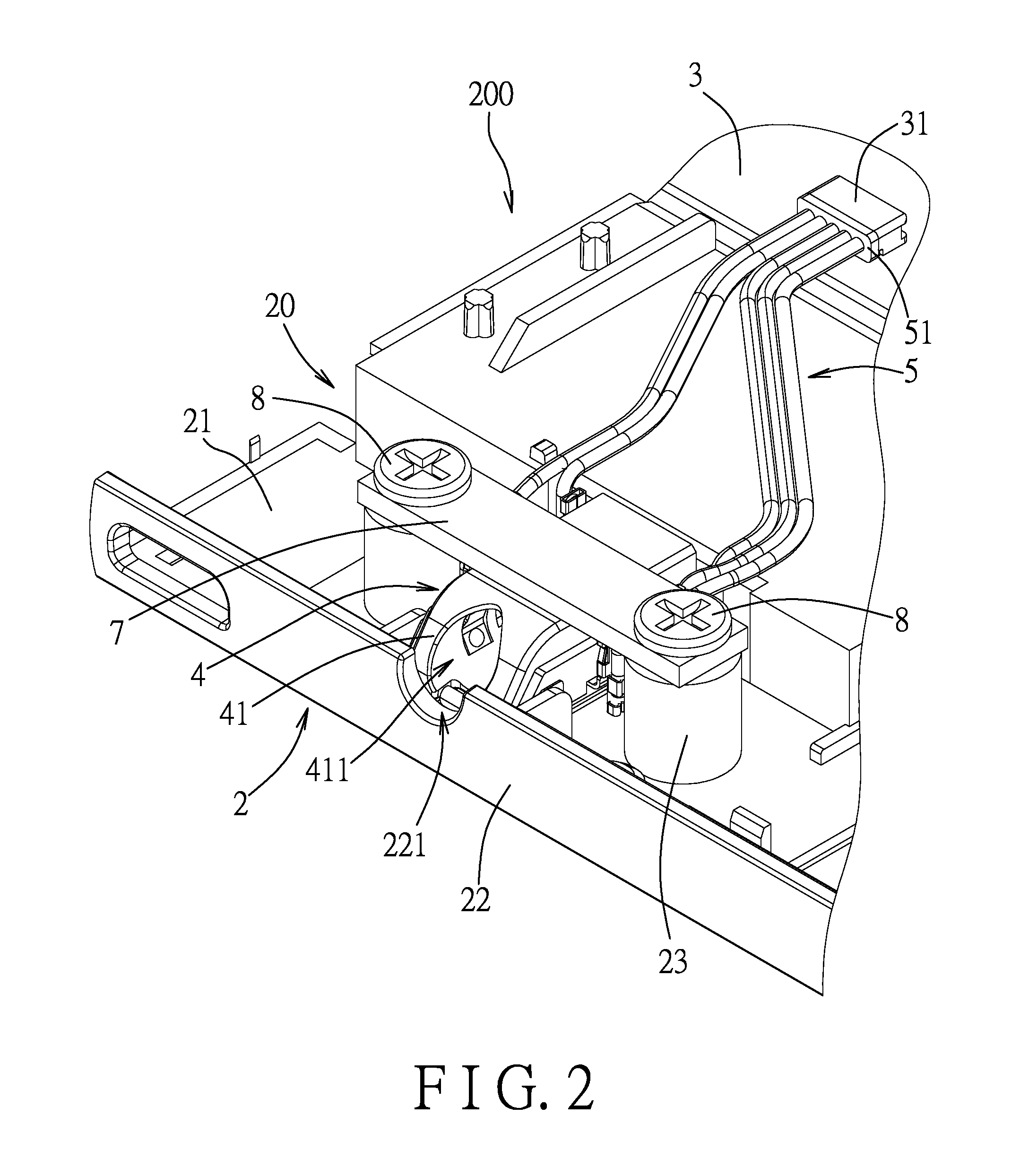
[0040]Referring to FIGS. 2 and 3, an electronic device 200 according to this disclosure is shown to include a shell body 2, a mother board 3, an electrical connector 4, a cable unit 5, and a plurality of adapter terminals 6.

[0041]Referring to FIGS. 2, 3, 4, and 5, the shell body 2 is formed with a receiving space 20. The shell body 2 includes a bottom wall 21, and a side wall 22 connected to a side of the bottom wall 21. The side wall 22 is formed with an opening 221 that is in spatial communication with the receiving space 20. The mother board 3 is disposed within the receiving space 20 and includes a socket connector 31.

[0042]The electrical connector 4 in this embodiment is illustrated using an audio connector. The electrical connector 4 is disposed in the receiving space 20, and is disposed on the bottom wall 21 and proximate to the side wall 22. The electrical connector 4 includes an insulator body 41 and a plurality of conductive terminals 42 disposed at the insulator body 41. ...

second embodiment

[0056]Referring to FIGS. 13 and 14, an electronic device according to this disclosure is illustrated to include adapter terminals 6′ which have a structure slightly different from that of the adapter terminals 6 used in the first embodiment.

[0057]In the second embodiment, in each of the adapter terminals 6′, the two first gripping plates 63 are positioned between the two second gripping plates 64 and the two sleeve plates 62. Each of the cables 52 is inserted along an upward installing direction (II) opposite to the downward assembling direction (I) to be disposed between the two first gripping plates 63 and between the two second gripping plates 64 so that the two first gripping plates 63 and the two second gripping plates 64 correspondingly grip the core wire 521 and the insulator sheath 522 of the cable 52.

[0058]In view of the aforesaid, in the disclosed embodiments, each of the adapter terminals 6, 6′ is connected to the core wire 521 of the corresponding one of the cables and i...


PUM


Abstract

An assembly includes an electrical connector, a cable unit, and adapter terminals. The electrical connector includes an insulator body and conductive terminals disposed at the insulator body. Each conductive terminal includes an insert arm positioned outside the insulator body. The cable unit includes a plug connector and cables connected to the plug connector. Each of the adapter terminals is connected to a core wire of a corresponding cable and is sleeved on the insert arm of a corresponding conductive terminal. Each adapter terminal is electrically connected between the core wire of the corresponding cable and the insert arm of the corresponding conductive terminal.

Description

CROSS-REFERENCE TO RELATED APPLICATION[0001]This application claims priority of Taiwanese Application No. 102220092, filed on Oct. 29, 2013, the entire disclosure of which is incorporated herein by reference.BACKGROUND OF THE DISCLOSURE[0002]1. Field of the Disclosure[0003]The disclosure relates to an assembly of an electrical connector and a cable unit, more particularly to an assembly of an electrical connector and a cable unit in which a plurality of conductive terminals of the electrical connector are electrically connected to a plurality of cables of the cable unit via a plurality of adapter terminals therebetween. The disclosure also relates to an electronic device including the assembly.[0004]2. Description of the Related Art[0005]Referring to FIG. 1, a presently available electronic device 1, for example, a notebook computer or a tablet computer, includes a shell body 11, a mother board 12 disposed within the shell body 11, and an audio connector 13 disposed within the shell...

Claims


Application Information

Patent Timeline
Patent Type & Authority Applications(United States)
IPC IPC(8): H01R4/18
CPCH01R4/18H01R11/22H01R24/58H01R31/06
Inventor LIU, YU-JULIU, CHE-WENHSIAO, JUI-LIN
Owner WISTRON CORP
Learn More