Motor Structure with a Brake Device

a technology of brake device and brake structure, which is applied in the direction of mechanical energy handling, electrical apparatus, dynamo-electric machines, etc., can solve the problems of complex structure and many components of the connection structure between the conventional torque motor and the brake device, so as to reduce the number of components of the present invention, improve assembly convenience, and reduce the cost

Inactive Publication Date: 2008-07-10
HIWIN MIKROSYST
View PDF1 Cites 2 Cited by
  • Summary
  • Abstract
  • Description
  • Claims
  • Application Information

AI Technical Summary

Benefits of technology

[0009]The primary objective of the present invention is to provide a motor structure with a brake device, wherein a hollow passage surface is formed in a side of the rotor, at a lower end of the hollow passage surface is formed a connecting portion, the brake device is located at the lower end of the base and connected to the connecting portion, so that the brake device is connected directly to the rotor. Since the brake device is directly connected to the connecting portion of the rotor, the number of components of the present invention is considerably reduced, thus reducing the cost while improving the assembly convenience and improving the operation stability of the motor.

Problems solved by technology

It is to be noted that the connection structure between the conventional torque motor and the brake device not only has many components but also is complicated in structure.

Method used


Image

  • Motor Structure with a Brake Device
  • Motor Structure with a Brake Device
  • Motor Structure with a Brake Device

Examples


Embodiment Construction

[0012]The present invention will be more clear from the following description when viewed together with the accompanying drawings, which show, for purpose of illustrations only, the preferred embodiment in accordance with the present invention.

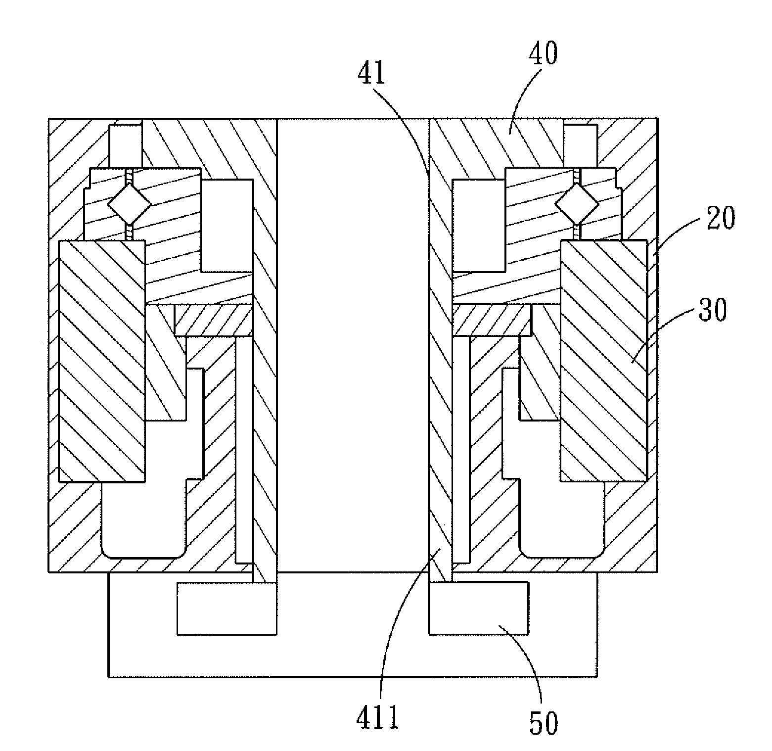
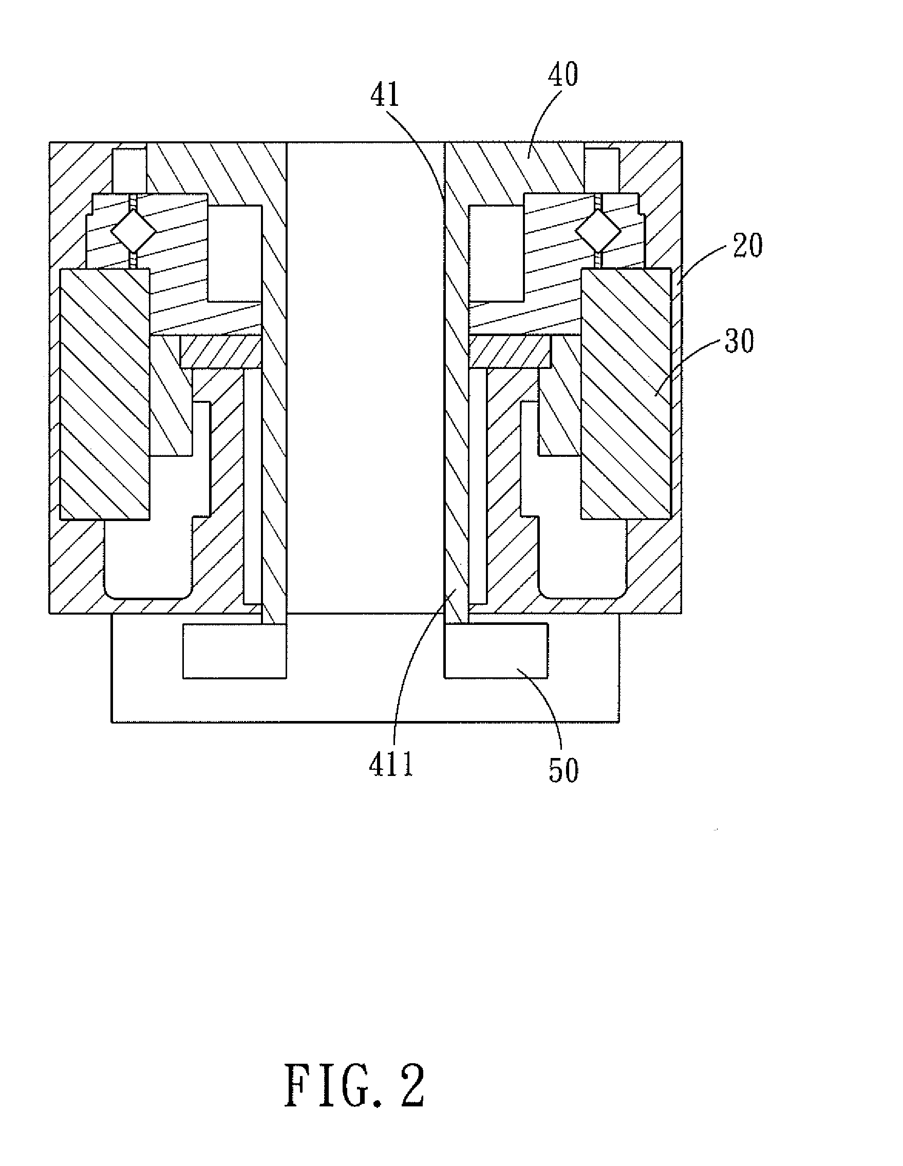
[0013]Referring to FIG. 2, a motor structure with a brake device in accordance with the present invention comprises: a base 20, a stator 30, a rotor 40, and a brake device 50.

[0014]The base 20 is a mounting frame on which the respective components of the motor are to be mounted.

[0015]The stator 30 is a hollow annular structure fixed in the base 20 and serves as a magnetic field generating structure for the motor.

[0016]The rotor 40 is rotatably disposed in the base 20 and is located inside the stator 30 and is rotatable relative to the stator 30. The rotor 40 is a magnetic field rotating member for the motor and is an annular hollow structure. In the inner surface of the rotor 40 is defined a hollow passage surface 41, and at the lower end of t...


PUM


Abstract

A motor structure with a brake device comprises a base, a stator, a rotor, and a brake device. A hollow passage surface is formed in a side of the rotor, at a lower end of the hollow passage surface is formed a connecting portion, the brake device is located at the lower end of the base and connected to the connecting portion, so that the brake device is connected directly to the rotor. Since the brake device is directly connected to the connecting portion of the rotor, the number of components of the present invention is considerably reduced, thus reducing the cost while improving the assembly convenience and improving the operation stability of the motor.

Description

BACKGROUND OF THE INVENTION[0001]1. Field of the Invention[0002]The present invention relates to a motor structure with a brake device, and more particularly to a connection structure design between a torque motor and the brake device.[0003]2. Description of the Prior Art[0004]Currently, rotating platforms are used in various equipments or mechanism, such as: wafer inspection equipment, automatic equipment, indexing plate, and all these equipments need a rotating platform. The rotating platform employs a torque motor as a rotating mechanism. And in order to meet the operation requirement, the torque motor is usually provided with a brake device which is employed to carry out deceleration and brake operation for the rotating platform.[0005]With reference to FIG. 1, a conventional torque motor with brake device is provided with a rotor 10 and a stator 11 that are concentrically arranged. A brake device 12 is disposed at the lower end of the motor, and disposed on the upper end of the ...

Claims


Application Information

Patent Timeline
Patent Type & Authority Applications(United States)
IPC IPC(8): H02K7/102
CPCH02K26/00H02K7/1025
Inventor WANG, CHIH-YU
Owner HIWIN MIKROSYST
Why Eureka
Try Eureka