Non-contact card reader

a card reader and non-contact technology, applied in the field of cards, can solve the problems of not being able to change the angle of an entire module, and requiring more time and costs in this solution, so as to simplify the processing procedure, reduce costs, and simply install

Active Publication Date: 2018-02-27
UNIFORM INDAL CORP
View PDF5 Cites 2 Cited by
  • Summary
  • Abstract
  • Description
  • Claims
  • Application Information

AI Technical Summary

Benefits of technology

[0017]Multiple light pipes are combined between a first board and a second board of an antenna module. After the antenna module is installed on a panel housing, a total thickness is relatively small, and is merely a thickness of the panel housing plus a thickness of the antenna module. The antenna module may be produced, and assembled in a modular manner in advance to simplify a processing procedure and reduce costs, and can be simply installed in different types of panel housings, thereby improving assembling convenience. In this way, the antenna module is applicable to panel housings having different shapes. Moreover, a panel housing may be assembled and combined with the antenna module while no excessively complex structure is designed inside the panel housing.

Problems solved by technology

Therefore, it is not allowed to change any angle of an entire module to satisfy different appearance requirements of a non-contact card reader.
Therefore, a disposing direction and appearance variance of a product are limited, and more time and costs are needed in this solution.
Moreover, when the antenna module D1 / D2 / D3 is installed by uniformly using one disposing direction, the antenna module D1 / D2 / D3 cannot be applied to multiple types of non-contact card readers.
Consequently, processing procedures and costs of the multiple types of antenna modules D1 / D2 / D3 are increased.

Method used


Image

  • Non-contact card reader
  • Non-contact card reader
  • Non-contact card reader

Examples


Embodiment Construction

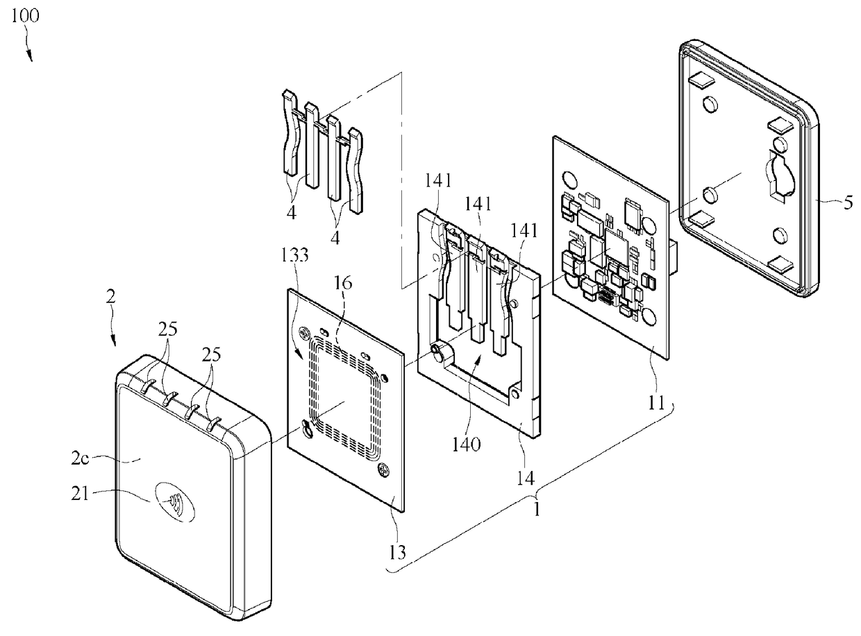
[0029]Referring to FIG. 4 and FIG. 5, FIG. 4 and FIG. 5 show a first embodiment of a non-contact card reader 100 of the present invention. A square housing 2c is used as a panel housing 2 of the first embodiment for description. FIG. 4 is a schematic exploded front view. FIG. 5 is a schematic exploded rear view. The non-contact card reader 100 of the present invention is configured to read a non-contact card. The non-contact card is a radio frequency identification (RFID) chip. The non-contact card is a ticket, a cash card, a financial card, or a credit card. The non-contact card reader 100 generates a current by means of electromagnetic induction and actuates the non-contact card. The non-contact card transmits an analog signal.

[0030]Referring to FIG. 4, in this embodiment, the non-contact card reader 100 includes an antenna module 1 and multiple light pipes 4. The antenna module 1 includes a first board 11, a second board 13, an antenna 16, and multiple light-emitting components 1...


PUM


Abstract

A non-contact card reader is provided, including: an antenna module, a spacer, multiple light pipes, and a panel housing. The antenna module includes a first board, a second board, an antenna, and multiple light-emitting components. The second board includes a surrounding area in which the antenna is disposed and a central area that is located at a center of the surrounding area and in which the multiple light-emitting components are disposed. The spacer is combined with the multiple light pipes and disposed between the first board and the second board. A single type of antenna module may be installed in the vertical housing, the horizontal housing, or the square housing of the panel housing in a fixed direction, thereby improving applicability of the antenna module.

Description

CROSS-REFERENCE TO RELATED APPLICATION[0001]This non-provisional application claims priority under 35 U.S.C. § 119(a) to Patent Application No. 105220009 filed in Taiwan, R.O.C. on Dec. 29, 2016, the entire contents of which are hereby incorporated by reference.BACKGROUNDTechnical Field[0002]The present invention relates to a card reader, and in particular, to a non-contact card reader.Related Art[0003]With development of science and technologies, a health insurance card, a credit card, a financial card, an identity card, a passport, and the like that need to be used in daily life are developed into magnetic stripe cards or digital identification cards having an IC chip. Some materials of a user are recorded on the digital identification cards. For example, a non-contact travel payment system is used in a ticket system. In recent years, because a technology of a radio frequency identification (RFID) system becomes gradually mature, many credit cards and financial cards show up on th...

Claims


Application Information

Patent Timeline
Patent Type & Authority Patents(United States)
IPC IPC(8): G06K7/10
CPCG06K7/10297G06K7/10316G06K7/10821G06K7/10722
Inventor CHEN, YU-TSUNGWU, CHUN-YIN
Owner UNIFORM INDAL CORP
Why Eureka
Try Eureka