Spirometer

a spirometer and spirometer technology, applied in the field of spirometers, can solve the problems of short and straight air flow path, limited response of a turbine-based spirometer at low flow rate, and limit the turbine's ability to respond to very low flow ra

Inactive Publication Date: 2015-04-30
MEDCHIP SOLUTIONS
View PDF2 Cites 9 Cited by
  • Summary
  • Abstract
  • Description
  • Claims
  • Application Information

AI Technical Summary

Benefits of technology

[0011]The present invention aims to provide an improved turbine-based spirometer in which the vane can freely rotate at low flow volumes.

Problems solved by technology

This results in a short and straight air flow path.
Nevertheless, the response of a turbine-based spirometer at low flow rate is limited by friction in these supporting bearings.
Further, any imbalance in the vane assembly limits the turbine's ability to respond to very low flow rates.
Since the torque on the vane is proportional to the flow, at low flow rates there is a correspondingly low torque available to turn the vane assembly.
This means that if there is imbalance in the vane then the low torque may be insufficient to raise a heavier side of an unbalanced vane and the rotation will cease whilst the heavier side is below the pivot when the axis of the turbine is horizontal.
This means that some of the available torque is lost as the pivot rolls up the inside cone of the V-jewel bearing rather than in the nadir of the V.

Method used


Image

  • Spirometer
  • Spirometer
  • Spirometer

Examples


Embodiment Construction

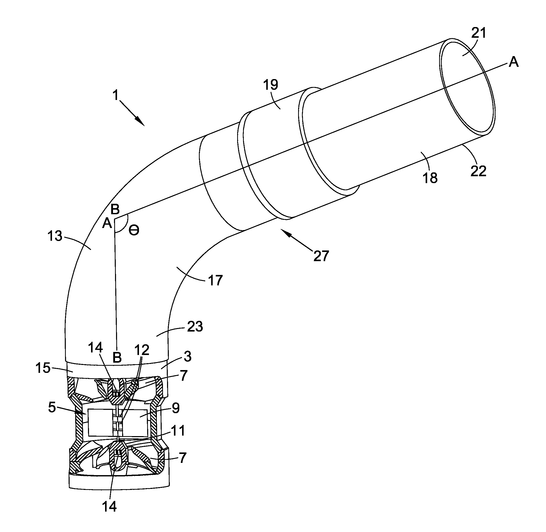
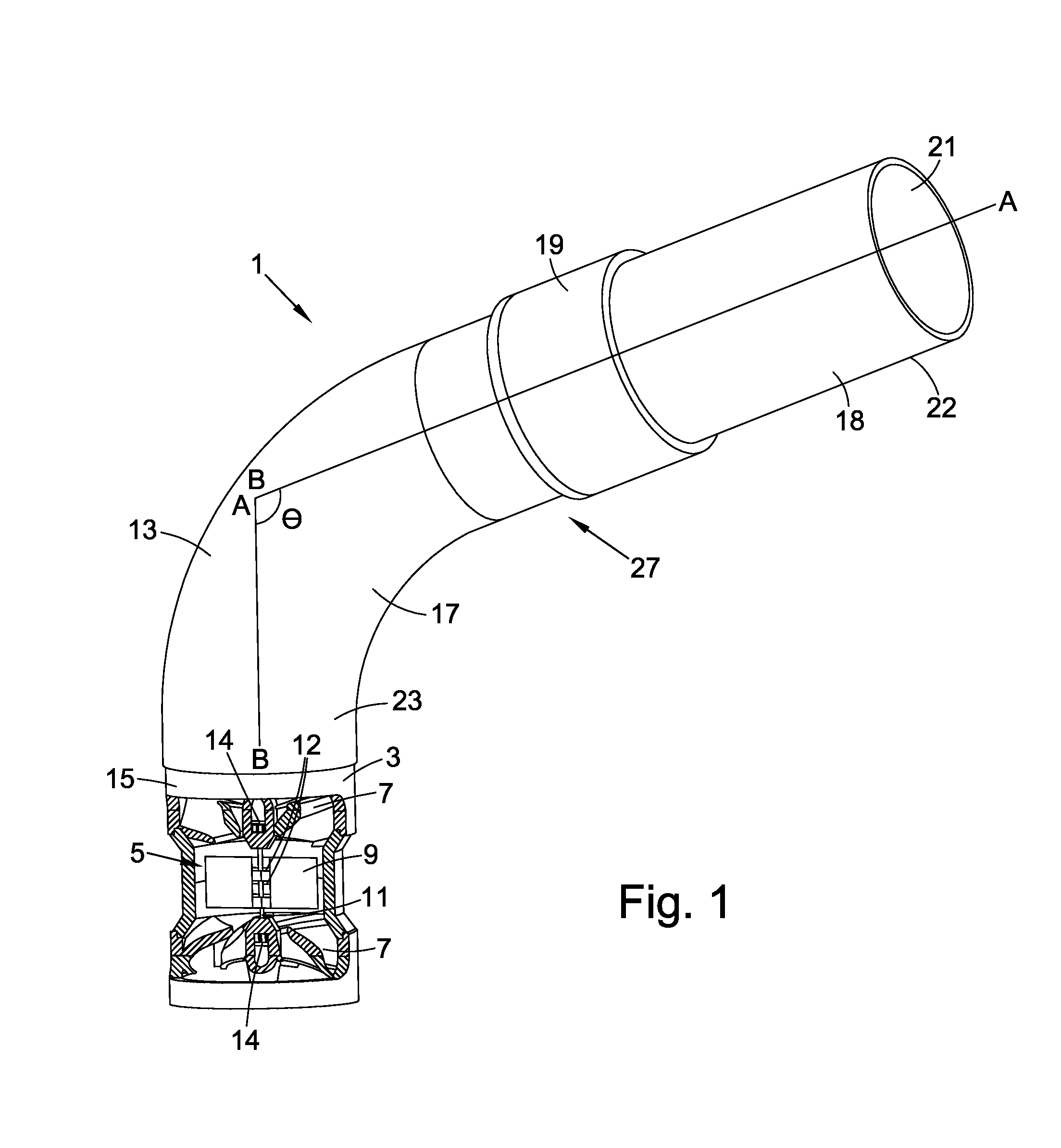
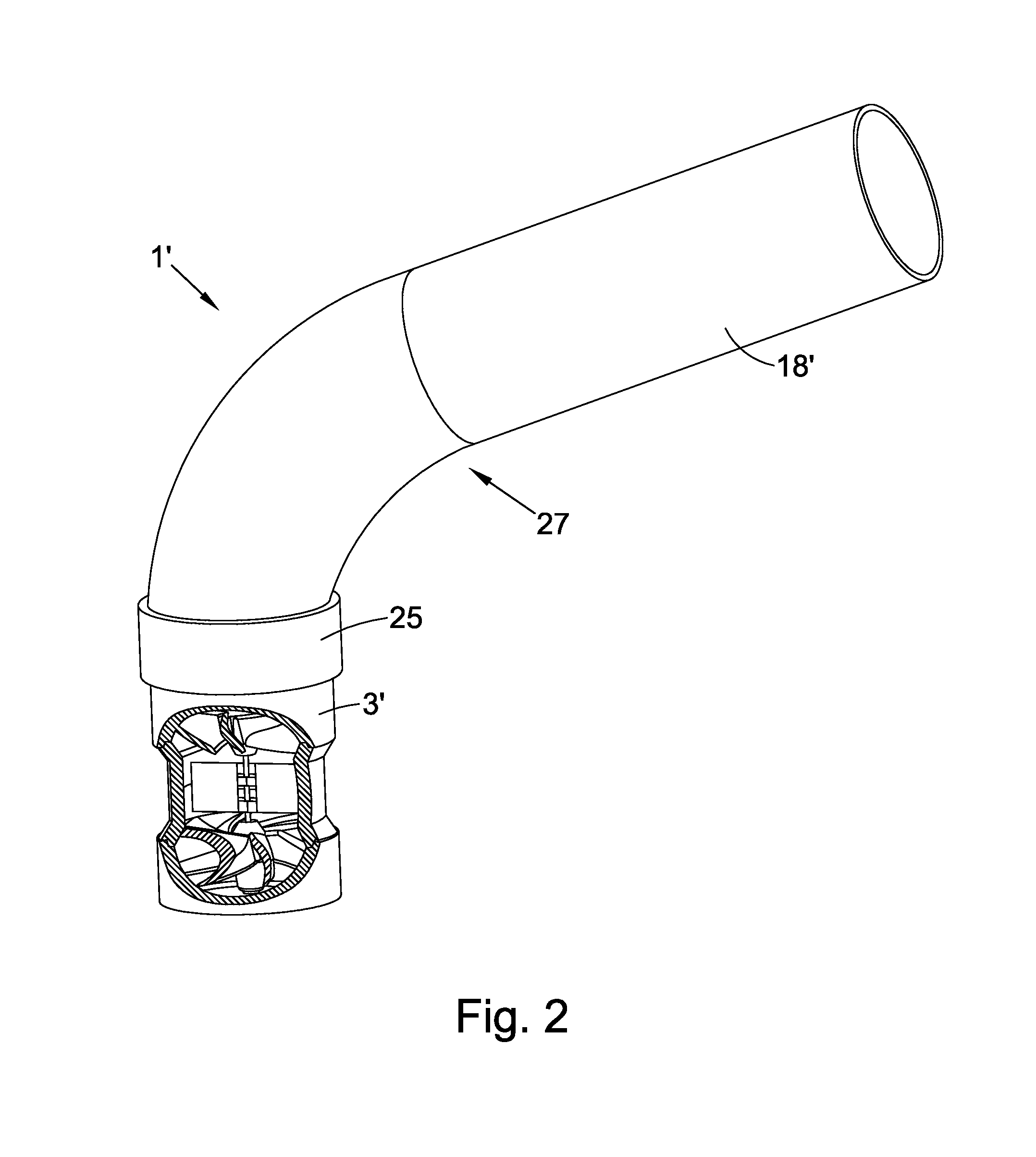
[0024]In FIG. 1, a spirometer 1 comprises a turbine assembly housing 3 in which is mounted a vane assembly 5 and two swirl plates 7. The turbine assembly housing 3 is partially cut-away to show part of the vane assembly 5 and the swirl plates 7. The vane assembly 5 comprises a vane 9 mounted on a shaft 11. The vane 9 is made of a rectangular flat / two-dimensional piece of thin plastic film and typically weighs around 0.07 g. The vane 9 has slits 12 in its centre through which the shaft 11 is threaded. The ends of the shaft 11 rest in respective V-jewel bearings 14 in each of the swirl plates. The vane 9 and shaft 11 are mounted in the swirl plates 7 so as to rotate in the turbine assembly housing 3 about the shaft 11 as air impels the vane. The moment of inertia of the vane assembly 5 is around 0.015 g.mm2.

[0025]The spirometer 1 further comprises a bent tube 13 which is attached to the upper end 15 of the turbine assembly housing 3. The bent tube 13 has a generally circular cross sec...


PUM


Abstract

A turbine spirometer comprises a breathing tube into which is subject is to breath and a vane to be driven by the subject's breath. The breathing tube has a first axis A-A at its opening in the direction of air flow and the vane rotates about a second axis B-B. The first A-A and second B-B axes are inclined to one another at angle of around 100 degrees such that in use the axis of rotation B-B is substantially vertical.

Description

CROSS-REFERENCE TO RELATED APPLICATIONS[0001]This application is a National Stage application of International Application No. PCT / GB2013 / 050743, filed Mar. 21, 2013, which claims benefit to Great Britain Application No. GB1205952.3, filed Apr. 3, 2012, which are incorporated by reference herein in their entirety.BACKGROUND[0002]1. Field[0003]This invention relates to a spirometer and in particular to a turbine spirometer.[0004]A spirometer is a medical diagnostic device that measures the flow and volume of a subject's forced exhaled and / or inhaled breath. Spirometers are used to diagnose common respiratory diseases. Examples of such diseases are asthma and Chronic Obstructive Pulmonary Disease (COPD).[0005]2. Description of the Related Art[0006]Turbine spirometers have been available since the mid-1980s. An example of a turbine spirometer is described in UK patent application published as GB-A-2224567, in the name of Micro Medical Limited.[0007]Turbine-based spirometers include a m...

Claims


Application Information

Patent Timeline
Patent Type & Authority Applications(United States)
IPC IPC(8): A61B5/09A61B5/097
CPCA61B5/097A61B5/09G01F1/103G01F1/12G01F15/028G01F15/04A61B5/091
Inventor LAWSON, CHRISTOPHERFOXWELL, IAN
Owner MEDCHIP SOLUTIONS
Why Eureka
Try Eureka