Device for transporting viscous compounds and pastes

Inactive Publication Date: 2015-05-14
LIST HLDG AG
View PDF8 Cites 0 Cited by
  • Summary
  • Abstract
  • Description
  • Claims
  • Application Information

AI Technical Summary

Benefits of technology

[0033]In the case of single-shaft kneaders, the winding angle and the angle of attack can be decoupled as desired. This does not result in a structural complication. In the case of multiple-shaft kneaders, it has to be noted that the engaging elements do not engage tangentially in the shaft movement, but rather dip into the shaft movement of the countershaft and exit again after a defined rotary angle. Rotation of the bars with respect to the winding of the shaft is therefore impossible if the knead

Problems solved by technology

Rotation of the bars with respect to the winding of the shaft is therefore impossible

Method used


Image

  • Device for transporting viscous compounds and pastes
  • Device for transporting viscous compounds and pastes
  • Device for transporting viscous compounds and pastes

Examples


Embodiment Construction

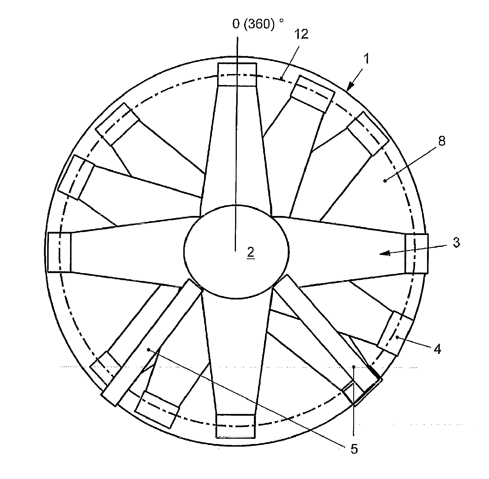
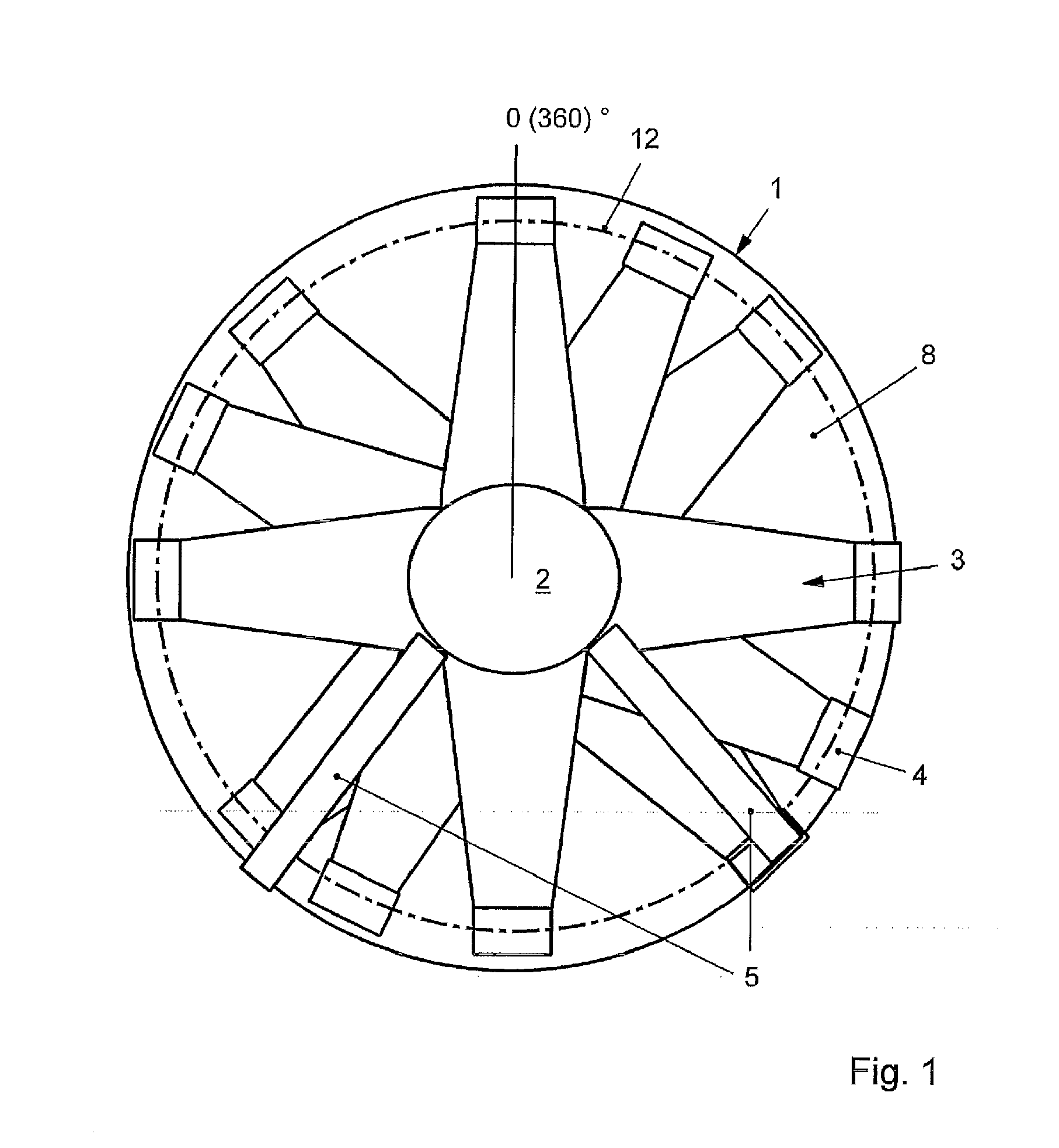
[0039]According to FIG. 1, a shaft 2 rotates in a housing 1, on which shaft 2 disk elements 3 are arranged. Transport bars 4 which wipe a housing inner wall are placed on said disk elements 3.

[0040]The transport bars 4 and disk elements 3 interact with static components 5 which protrude from the housing inner wall into a product space 8 against the shaft 2.

[0041]Using a dash-dotted line, 12 indicates a sectional plane with a viewing direction for the following FIGS. 2 to 4.

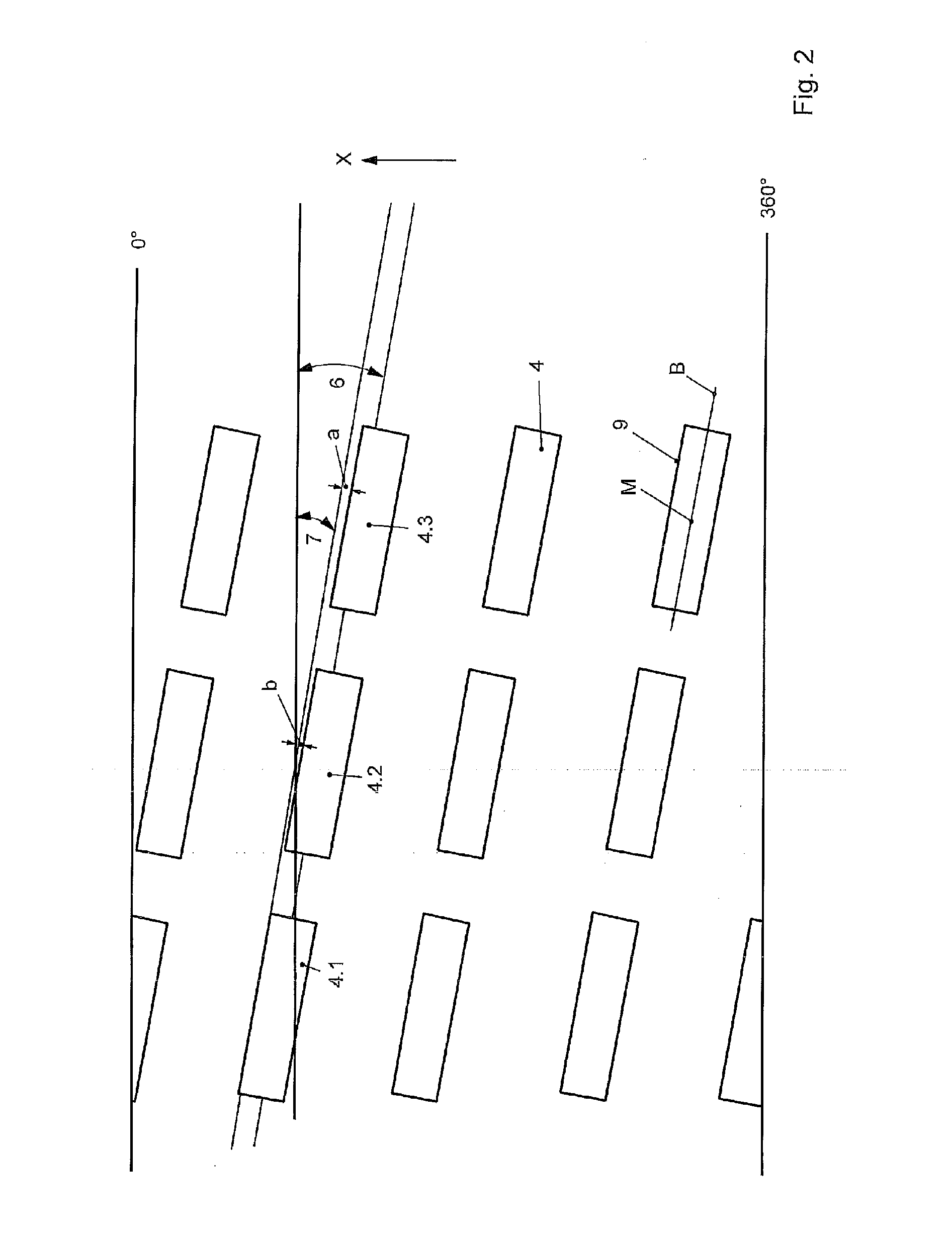
[0042]The shaft 2 rotates about a shaft axis A. Each transport bar 4 has a center axis B which runs through a center point M of the transport bar 4. The center axis B is set at an angle against the shaft axis A.

[0043]A surface 9 of the kneading bar 4 runs at an angle 7 which is to be called the conveying angle. In the exemplary embodiment according to FIG. 2, the surface 9 runs approximately parallel to the center axis B. However, the surfaces 9 of transport bars 4 which follow one another are arranged offset in e...


PUM

PropertyMeasurementUnit
Angleaaaaaaaaaa
Viscosityaaaaaaaaaa

Abstract

A device for the controlled transport of viscous compounds and pastes in at least one process space (8) by at least one shaft (2), on which transport bars (4) are arranged and which rotates about a shaft axis (A), wherein centre axes (B) of the transport bars (4) run at an angle (7) with respect to the shaft axis (A), the centre axes (B) of transport bars (4.1, 4.2, 4.3) which follow one another in the direction of the shaft axis (A) should run offset in the circumferential direction with respect to one another and with respect to the shaft axis (A).

Description

BACKGROUND OF THE INVENTION[0001]The invention relates to a mixing kneader.[0002]In process technology, stirred containers for reaction control or for thermal processes have been customary for a long time. If the stirred vessel is operated continuously, it is desirable for it to be possible to set the level of filling in the stirred vessel, since the pressure vessel can otherwise be overfilled or underfilled, or the starting material or product would be subjected to different dwell times in the stirred vessel. The setting of the level of filling takes place gravimetrically either via a weir, over which the product flows, or by means of a pump solution with a filling level probe.[0003]In the case of viscous compounds or pastes, the gravimetric filling level control does not function, since the stirrer has to be configured in such a way that it forcibly delivers the product or starting material. Here, the forces which are produced during the forced conveying are greater than the gravi...

Claims


Application Information

Patent Timeline
IPC IPC(8): B29B7/80B29B7/40
CPCB29B7/40B29B7/802B01F27/0726B01F27/091B01F27/707B01F27/70B01F27/00B01F27/701
Inventor WITTE, DANIEL
Owner LIST HLDG AG
Why Eureka
Try Eureka