
Hand-held power tool

a power tool and hand-held technology, applied in the field can solve the problems of affecting the use of hand-held power tools, the inability to lock the bayonet joint, and the loosening of the bayonet by itself,

Active Publication Date: 2019-11-19
ROBERT BOSCH GMBH
View PDF21 Cites 1 Cited by
  • Summary
  • Abstract
  • Description
  • Claims
  • Application Information

AI Technical Summary

Benefits of technology

The solution ensures a secure, lockable connection with minimal tilting clearance and unambiguous angular positioning, enhancing user safety and tool stability by providing a clear indication of the locking state, thus preventing damage and injuries.

Problems solved by technology

It is disadvantageous that the bayonet joint cannot be locked, so that it may come loose by itself due to vibrations occurring during operation of the hand-held power tool.
This may result in damage to the tool attachment and / or the hand-held power tool, as well as injury to a user of the hand-held power tool.
In addition, it has been found disadvantageous that there is no unambiguous, reproducible angular position of the locking element with respect to the tool housing in the locking state of the bayonet joint, so that the locking state cannot be unequivocally indicated.
With respect to the implementation with the aid of a bayonet joint, this in turn has the disadvantage that a large tilting clearance occurs in the interface between the tool attachment and the gear housing, which is undesirable.
In this approach as well, it is disadvantageous that there is no unambiguous, reproducible angular position of the locking element with respect to the gear housing, so that the locking state cannot be unequivocally indicated.

Method used


Image

  • Hand-held power tool
  • Hand-held power tool
  • Hand-held power tool

Examples


Embodiment Construction

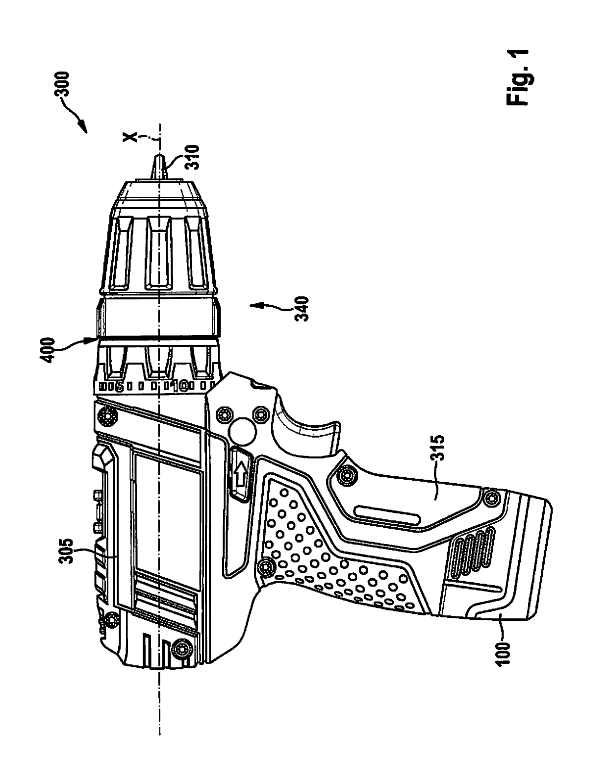
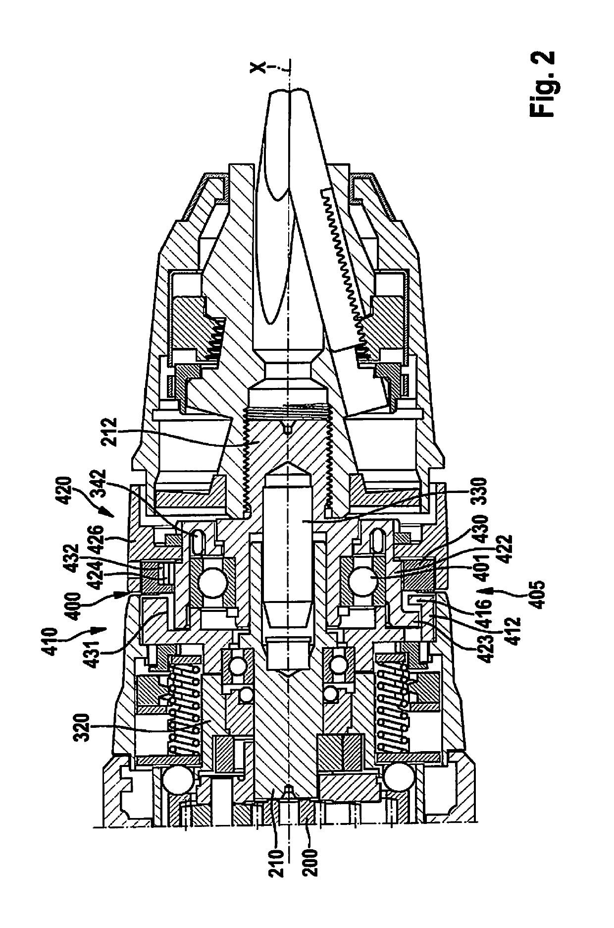
[0051]FIG. 1 illustrates an electrical device designed as a hand-held power tool 300. According to the illustrated specific embodiment, hand-held power tool 300 is mechanically and electrically connectable to rechargeable battery pack 100 for supplying power independently of the power grid. The hand-held power tool includes a handle 315 on which rechargeable battery pack 100 is situated in a locked manner. Hand-held power tool 300 is designed as a cordless screw drill as an example in FIG. 1. However, it is pointed out that the present invention is not limited to cordless screw drills, and instead may be used for various hand-held power tools 300 that are operated with electrical power. Hand-held power tool 300 includes a base body 305 that includes a gear housing 320 (FIG. 2). A tool attachment 340 is exchangeably connected at gear housing 320 via an interface 400. In the present case, tool attachment 340 is designed as a drill chuck tool holder that includes a tool receptacle 310 ...


PUM

PropertyMeasurementUnit
slope angleaaaaaaaaaa
torqueaaaaaaaaaa
rotation angleaaaaaaaaaa

Abstract

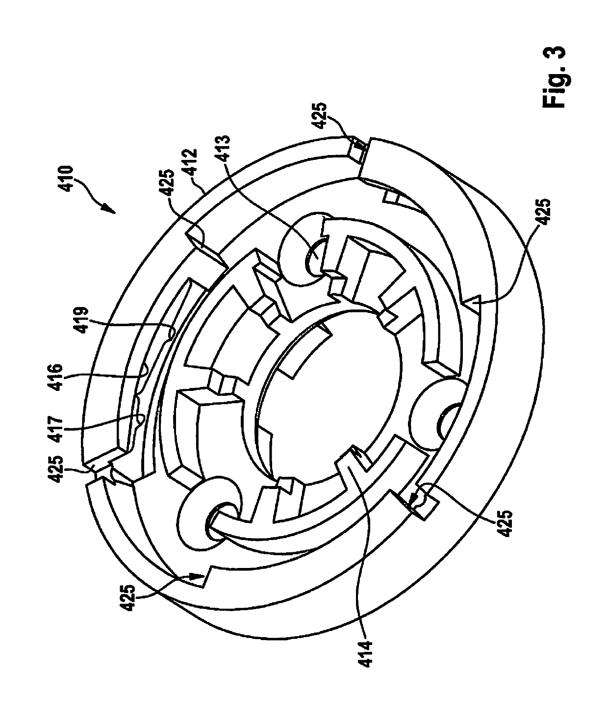
A hand-held power tool which includes a gear housing with a gear for transmitting a torque, generated by a drive motor, to a spindle. The gear housing is exchangeably connectable to a tool attachment via an interface in such a way that a torque is transmitted from the spindle to an input spindle of the tool attachment. The interface includes a housing-side interface element with a flange ring, which is connected to the gear housing in a torsionally stiff manner. The housing-side interface element corresponds to a tool attachment-side interface element which includes a fastening ring that is rotatably supported on the tool attachment. The fastening ring is brought into engagement with the flange ring by a coupled rotatory and axial relative movement of the fastening ring with respect to the flange ring so that the fastening ring and the flange ring together form a bayonet-type connector.

Description

FIELD[0001]The present invention relates to a hand-held power tool, a tool attachment for a hand-held power tool, as well as a tool system that includes a hand-held power tool, and a tool attachment.BACKGROUND INFORMATION[0002]Hand-held power tools, such as cordless screw drills or drills, are conventional. To increase the possible applications for a hand-held power tool such as a screwdriver or screw drill, a tool attachment is detachably mounted on the hand-held power tool. Thus, for example, conventional angle attachments have an output shaft that is situated at an angle with respect to the drive shaft of the hand-held power tool. Furthermore, in conventional eccentric attachments, the output shaft is offset in parallel to the drive shaft of the hand-held power tool.[0003]Various types of fastenings are available for detachably mounting a tool attachment on the housing of a hand-held power tool.[0004]German Patent Application No. DE 101 09 956 B4 describes a hand-held power tool ...

Claims


Application Information

Patent Timeline
Patent Type & Authority Patents(United States)
IPC IPC(8): B25F3/00B23B45/00
CPCB23B45/003B23B45/008B25F3/00B23B2231/04Y10T279/3412B23B2231/06
Inventor BRENNENSTUHL, JENSHOFFMANN-SUGLAND, MICHAELMOCK, STEFAN
Owner ROBERT BOSCH GMBH
Learn More