Knitting machine needle with loss-proof coupling component

a technology of coupling component and knitting machine needle, which is applied in the field of knitting machine needle, can solve the problems of missing needle foot, requiring considerable manual effort to load the small circular knitting machine, and improper needle activation, so as to achieve smooth movement bearing, good force transmission, and precise

Active Publication Date: 2011-07-05
GROZ BECKERT KG
View PDF11 Cites 0 Cited by
  • Summary
  • Abstract
  • Description
  • Claims
  • Application Information

AI Technical Summary

Benefits of technology

[0007]The above object generally is achieved according to the invention with a knitting machine needle having a needle body that is connected with a selecting member. The selecting member may also be configured as a coupling member. The connection used is a hinge arrangement or joint arrangement that, in one embodiment, comprises a coupling recess on the needle and a dial head arranged on the coupling member. Referring to another embodiment, the coupling recess is provided on the coupling member, whereas the dial head is formed on the needle body. In both cases, the dial head has a bearing surface on its circumference, said bearing surface being associated with a counter bearing surface provided on the coupling recess. As a result of this arrangement of the bearing surface and the counter bearing surface it is possible to achieve a precise, smooth-moving bearing with minimal play. Good force transmission from the coupling member to the needle body is achieved in longitudinal direction of the needle body, as well as in the driving-out direction and also in the retracting direction.
[0010]By configuring the hinge arrangement in the form of a dial head and an associate coupling recess, the coupling member is mostly coupled with the needle body in an X-direction. In order to ensure no loss in Z-direction, matching transverse bearing surfaces, said surfaces being at least temporarily in abutment with each other, are provided on the coupling member and on the needle body. These transverse bearing surfaces are in abutment with each other, at least when the coupling member and the needle body are in a swivel position relative to each other as is assumed when the coupling member and the needle are to be mounted in the rib dial or another in needle bed. For example, this is a position in which the coupling member is slightly inclined toward the height direction. This measure prevents the coupling member and the needle body to unintentionally fall apart during assembly, i.e., during installation in the needle bed. Handling of the unit consisting of the needle body and the coupling member is facilitated considerably.

Problems solved by technology

In addition, there is the risk that even a minimal lateral deflection of the selecting member can cause the needle foot to be missed by said selecting member and the needle to be activated in an improper manner.
Furthermore, loading the small circular knitting machine requires considerable manual effort because the selecting members and the rib needles must be handled separately.
As a result of this, assembly as well as disassembly of the knitting machine needle and of the selecting member or coupling member can be difficult.

Method used


Image

  • Knitting machine needle with loss-proof coupling component
  • Knitting machine needle with loss-proof coupling component
  • Knitting machine needle with loss-proof coupling component

Examples


Embodiment Construction

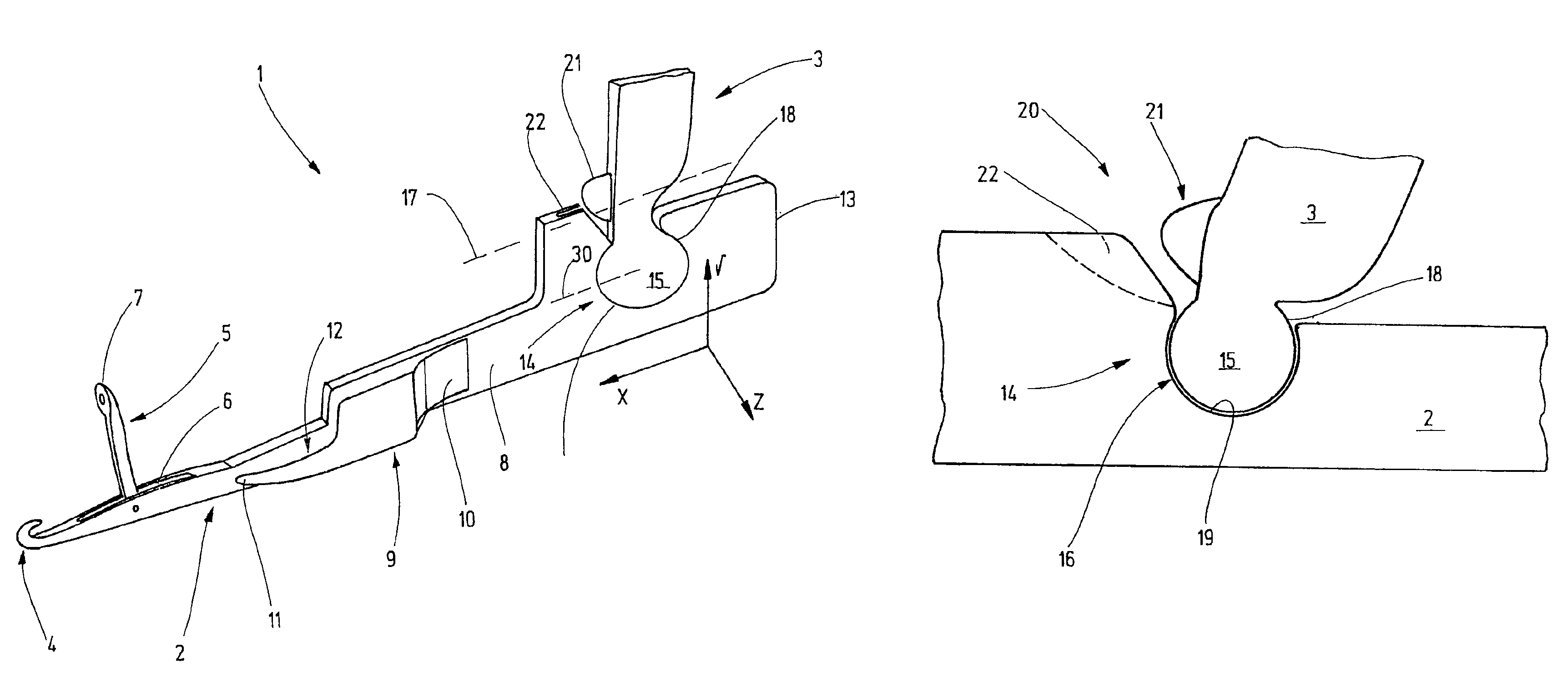
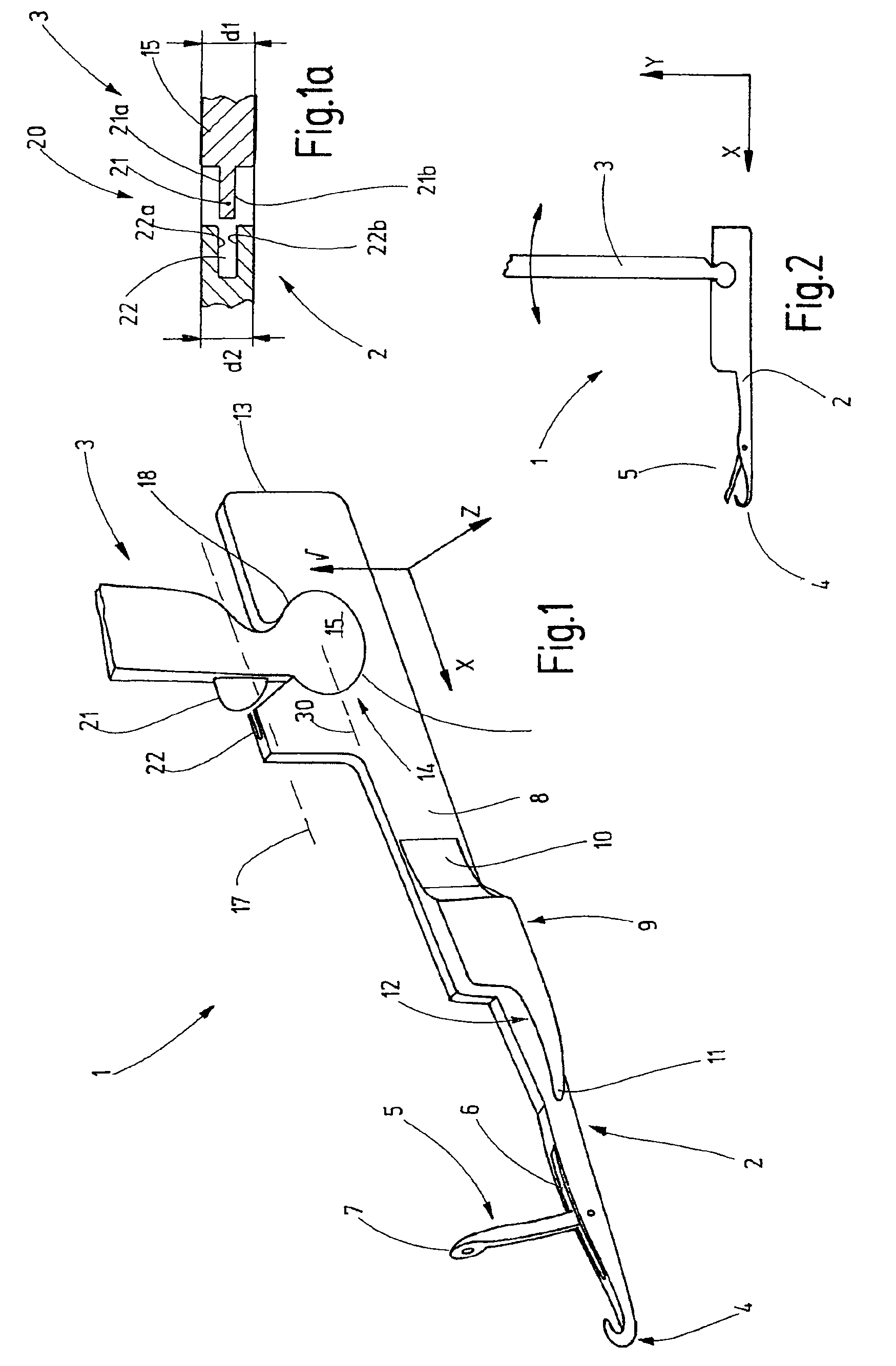
[0021]FIG. 1 shows a knitting machine needle 1 that is prepared for installation in a rib dial and may thus be referred to as a rib dial needle or a rib needle. However, the invention is not restricted to rib needles but can also be used on knitting machine needles that are not inserted in the rib dials.

[0022]The knitting machine needle 1 comprises a needle body 2 and a coupling member 3. Preferably, the needle body 2 is configured as an elongated flat part. On one end, said elongated flat part is provided with a hook 4 that is disposed to form stitches. The hook 4 may be associated with additional elements such as, for example, a latch 5 that is pivotally supported near the hook 4. This latch is pivotally supported in a latch slit 6 so that its end 7 can cover the point of the hook 4 and thus close the hook 4 or—also in rear position—can reach a position remote from the hook 4 in order to clear the hook 4.

[0023]A rehanging spring 9 may be provided on one flank 8 of the needle body ...


PUM


Abstract

In order to simplify handling of the knitting machine needles and of associate coupling members—in particular when loading the rib dials—a knitting machine needle with a coupling member that is pivotally supported on said knitting machine needle is being provided. The transverse bearing surfaces (21a) and (b), as well as (22a) and (b), said surfaces being at least temporarily in abutment with each other, are disposed to laterally secure the coupling member (3) on the needle body.

Description

CROSS-REFERENCE TO RELATED APPLICATION[0001]The present application claims the priority of European Patent Application No. 09 167 092.7, filed Aug. 3, 2009, the subject matter of which, in its entirety, is incorporated herein by reference.BACKGROUND OF THE INVENTION[0002]The invention relates to a knitting machine needle, in particular to a rib dial needle.[0003]In particular considering small circular knitting machines, conditions are restricted around the rib dial. The rib dial forms an annular bed for the accommodation of the rib dial needles that are also referred to as rib needles. Such a small circular knitting machine has been disclosed by WO 2009 / 013773 A1, for example. The knitting machine described therein comprises a knitting cylinder with vertically arranged cylinder needles and a rib dial with horizontally arranged rib needles. The rib needles are moved by a needle selecting mechanism that is located above the rib dial. The needle selecting mechanism acts on the rib nee...

Claims


Application Information

Patent Timeline
Patent Type & Authority Patents(United States)
IPC IPC(8): D04B35/02
CPCD04B35/02D04B35/04D04B15/00D04B35/00
Inventor HORN, KUNOSCHNEIDER, JURGEN
Owner GROZ BECKERT KG
Why Eureka
Try Eureka