
Mowing blade comprising a blade bar composed of bar sections

a technology of mowing blade and blade bar, which is applied in the direction of mowing machines, agriculture tools and machines, applications, etc., can solve the problems of buckling forces, high packaging and transportation costs, and thousand loading changes, and achieve the effect of improving the absorption of buckling forces

Inactive Publication Date: 2005-05-03
SCHUMACHER HEINRICH GUNTER
View PDF12 Cites 15 Cited by
  • Summary
  • Abstract
  • Description
  • Claims
  • Application Information

AI Technical Summary

Benefits of technology

The design effectively absorbs high forces and bending loads, reducing the risk of breakage and allowing for easier transportation by distributing loads across multiple blades and a high-strength connecting fish plate, maintaining structural integrity and simplifying section connection and exchange.

Problems solved by technology

Thus, transport is cumbersome from the manufacturer to the user of the machine in the field.
The cost of packaging and transport are, therefore, higher than the mowing sickle itself.
This leads to over a thousand loading changes.
The bending forces act especially on the connection points since the mowing sickle cannot be precisely vertically guided because of its length.
A disadvantage in this embodiment is due to the blades having a common width of 76.2 mm, four bores are arranged very close to each other.
No improvement is achieved, but danger of breakage exists in the area of the connection.
A further disadvantage is, since commonly used mowing blades have only two bores, special mowing blades are required with four through bores.
Furthermore, it is also possible, but only with low success and high expenditure, to heat treat the material in the area of the connection to provide improved strength to reduce the breakage danger.

Method used


Image

  • Mowing blade comprising a blade bar composed of bar sections
  • Mowing blade comprising a blade bar composed of bar sections
  • Mowing blade comprising a blade bar composed of bar sections

Examples


Embodiment Construction

[0019]The following description of the preferred embodiment(s) is merely exemplary in nature and is in no way intended to limit the invention, its application, or uses.

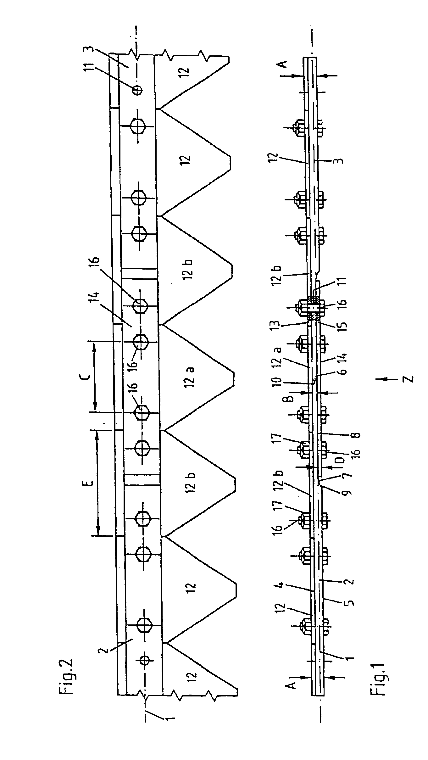
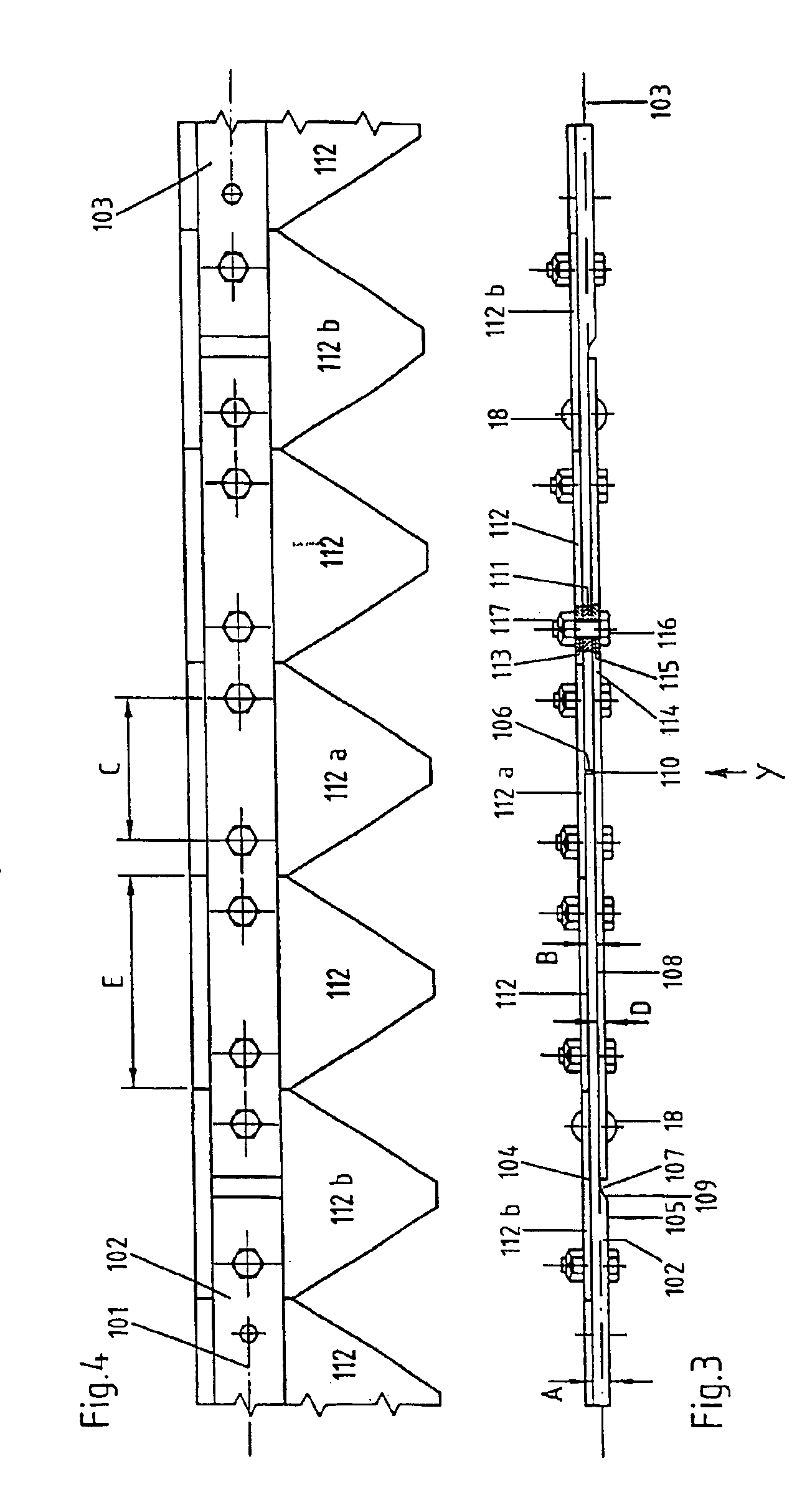
[0020]FIGS. 1 and 2 are described together in the following. FIGS. 1 and 2 only show a limited longitudinal portion of a mowing sickle. The butt joint of a two bar sections 2, 3 is represented in more detail. The two bar sections 2, 3 are arranged behind one another along the longitudinal axis 1. The two bar sections 2, 3 are formed identically in that area, in which they are connected to each other, so that only a description of the special design in this area in reference to the first bar section 2 is given.

[0021]The first bar section 2 is formed with a continuously flat attachment face 4. Further, it includes a second face 5 arranged parallel to the attachment face 4 defining a first distance A between the two faces. A third face 8 starts from a front face 6 and ends at a recess 7. A smaller distance in relation to...


PUM


Abstract

A mowing blade that performs an oscillating linear motion, has a blade bar, with at least two bar sections that are located one behind the other along a longitudinal axis. The front faces of the sections abut one another and have respective recesses. The thickness of the bar sections is reduced in recessed areas. A connecting fish plate, which can for example be constructed from a high strength material, is placed in the recesses. The blade sections, bar sections and fish plate are connected by cap screws and securing nuts. A blade section covers the butt joint between the two bar sections. The configuration enables absorption of inertial forces caused by the backwards and forwards reciprocating motion and compressive forces that result from the motion in the connection region.

Description

FIELD OF THE INVENTION[0001]The invention relates to an oscillating linear motion mowing sickle including a sickle bar. The sickle bar has at least two bar sections positioned one behind the other along a longitudinal axis. The at least two bar sections are connected to each other by a connection member.BACKGROUND OF THE INVENTION[0002]Mowing sickles are preferably used in harvesting machines, for example combine harvesters, to mow stem stock. Because of the immense mowing widths, mowing sickles are achieved with a length of 9 meters or more. The sickles are reciprocally moved by a drive. Blades attached to the sickle bar cut the harvesting crop against fingers which form counter cutting edges. Depending on use, the blades undergo more or less strong wear. During harvesting, the blades and even the whole mowing sickle often need to be exchanged. Mowing sickles with the above stated length are quite flexible as the sickles generally have, in cross-section, a relatively thin rectangul...

Claims


Application Information

Patent Timeline
Patent Type & Authority Patents(United States)
IPC IPC(8): A01D34/02A01D34/14
CPCA01D34/14
Inventor SCHUMACHER, HEINRICH-GUNTER
Owner SCHUMACHER HEINRICH GUNTER
Learn More