Retaining system for a movable component

a technology of movable components and retaining systems, which is applied in the direction of seating arrangements, transportation and packaging, aircraft crew accommodation, etc., can solve the problems that the manual activation bolts for locking the bathroom door are often unable to transmit additional forces

Active Publication Date: 2017-02-16
AIRBUS OPERATIONS GMBH
View PDF16 Cites 15 Cited by
  • Summary
  • Abstract
  • Description
  • Claims
  • Application Information

AI Technical Summary

Benefits of technology

[0006]The advantage to situating the movable locking elements on the second retaining area, i.e., on the support structure, and not on the movable component itself, is that reinforced locking elements can also be provided, but do not also have to be moved while opening or moving the movable component. This enables a higher force transmission, and facilitates moving the movable component to the greatest extent possible. The movable component itself is provided with the locking receptacle, but the latter as a rule requires less weight and installation space, since it can be fixed in place, and does not require an additional movement mechanism, e.g., of the kind required for the at least one movable locking element. Because the locking elements are integrated into the fixed lateral part, e.g., a door frame, the movable component, e.g., a door leaf, is not weakened. In addition, arranging the movable locking elements in the lateral, fixed portion on the movable component eliminates the need to set aside or budget for corresponding installation space.
[0011]For example, this enables a lavatory door in which increased forces can be transmitted in the closed setting, and in which the door element itself can simultaneously be given a more lightweight design, since the movement mechanism for the locking elements is situated in the fixed portion, e.g., the door frame. The lavatory door serves as an access point to the lavatory room behind it.
[0023]For example, the seat involves a seat for flight attendants (so-called Cabin Attendant Seat, CAS, also referred to as Flight Attendant Seat, FAS), which only is used in certain phases of flight operation, e.g., during landing and takeoff, or also in the event of inflight turbulence. Also referred to as a Standard CAS, the CAS can be a defined structural unit not to be adapted, which is secured to the door by mechanical interfaces, and among other things comprises a seat or folding seat, which is attached to the Standard CAS structural unit by way of a hinge. The potential advantage to this arrangement is that less room is used overall for the vehicle attendant seat and lavatory. This leaves more room for a larger number or more generous distribution of passenger seats.
[0040]An aspect of the invention provides that the movable locking elements are situated on the fixed frame part on a movable element, for example a door element, and that the door element itself only comprises receptacles or other fixed, suitable counterparts to the locking elements. The movement mechanism for locking and unlocking is thus integrated into the frame construction. As a consequence, for example, a larger number and even more strongly designed locking elements can be provided without increasing the weight of the movable component, in particular a door.

Problems solved by technology

However, it was found that manually activated bolts for locking a bathroom door are often unable to transmit additional forces, i.e., higher forces.

Method used


Image

  • Retaining system for a movable component
  • Retaining system for a movable component
  • Retaining system for a movable component

Examples


Embodiment Construction

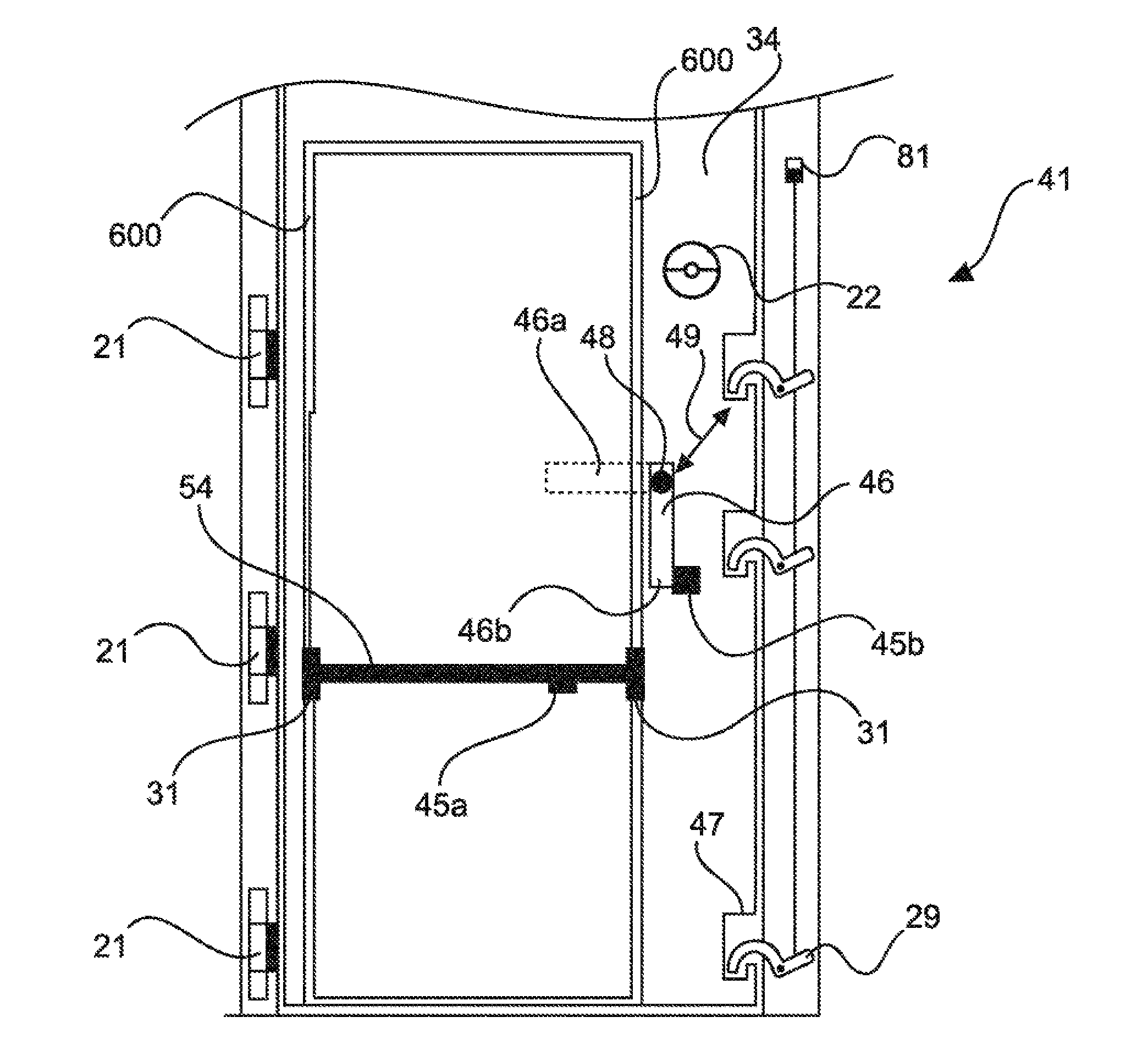
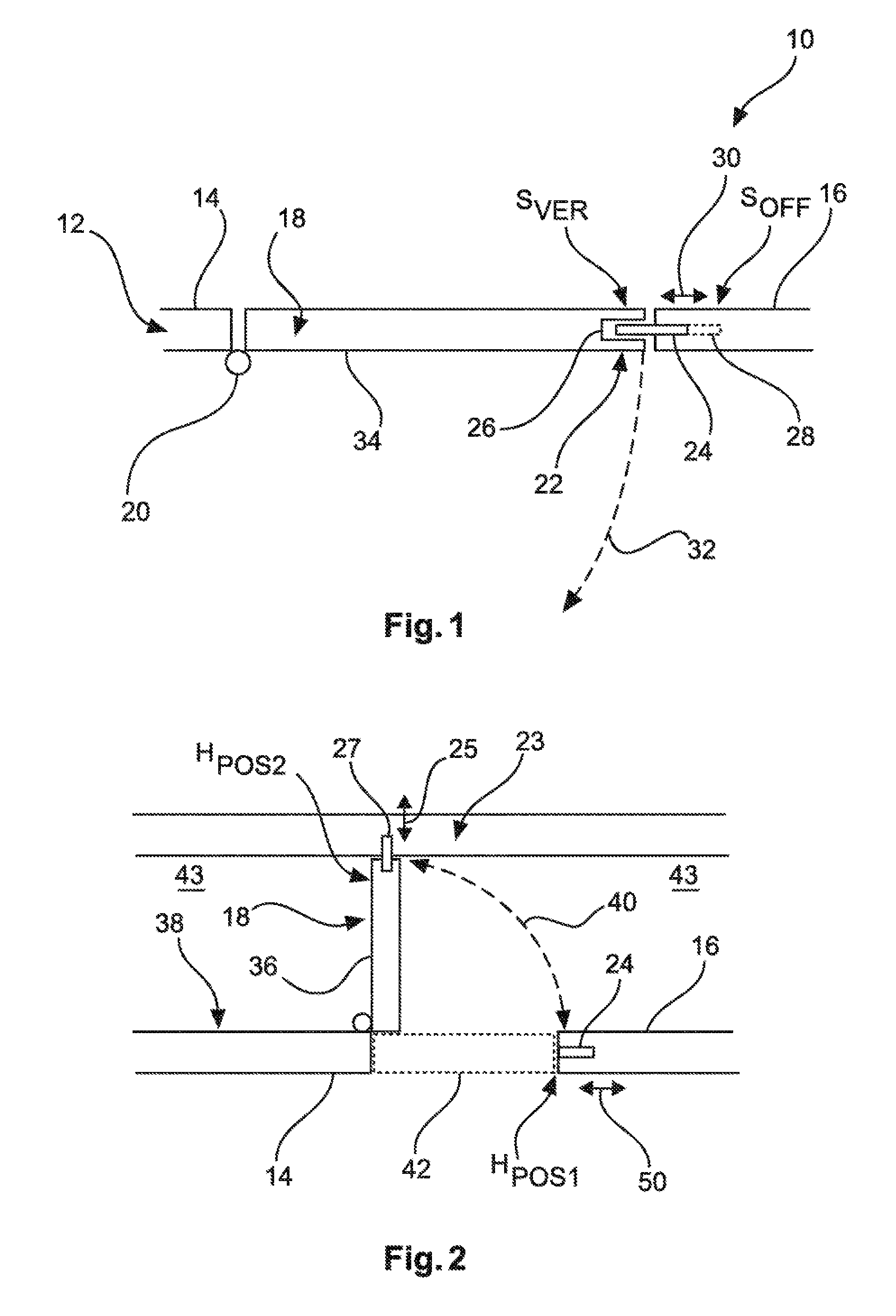
[0061]FIG. 1 shows a first example of a retaining system 10 for a movable component used to partition a room segment on board an aircraft. The retaining system 10 comprises a support structure 12 with a first retaining area 14 and a second retaining area 16. Additionally provided is a movable component 18 and a retaining device 20 and locking device 22. The movable component 18 is movably attached to the first retaining area 14 with the retaining device 20. The movable component 18 can be locked to the second holding area 16 (e.g., a doorpost or a wall element) with the locking device 22. For this purpose, the locking device comprises at least one movable locking element 24 and at least one locking receptacle 26. The at least one movable locking element 24 can move between a locked setting SVER and an open setting SOFF. FIG. 1 shows the movable locking element 24 in the locked setting SVER. The arrangement in the open setting SOFF is denoted by a dashed line 28. A double arrow 30 po...


PUM


Abstract

To be able to transmit higher forces when retaining movable components on board an aircraft, a retaining system includes a support structure with a first retaining area and a second retaining area having a movable locking element, and a movable component with a locking receptacle forming a locking device with the locking element, and a retaining device. The movable component is movably attached to the first retaining area with the retaining device, and the movable component can be locked on the second retaining area with the locking device. The at least one movable locking element can be moved between an open setting (SOFF) and a locked setting (SVER), wherein the at least one movable locking element engages with the locking receptacle in the locked setting, so that the movable component is temporarily immovably retained, and allows the movable component to move in the open setting.

Description

CROSS-REFERENCE TO RELATED APPLICATIONS[0001]This application is a continuation of International Application No. PCT / EP2015 / 057025 filed Mar. 31, 2015, published on Oct. 15, 2015, which claims priority from German Patent Application No. 10 2014 104 921.7 filed Apr. 7, 2014, all of which are incorporated herein by reference.FIELD OF THE INVENTION[0002]The present invention relates to retaining movable components on board an aircraft, and in particular relates to a retaining system for a movable component on board an aircraft, a module for a cabin in an aircraft, an aircraft, a method for locking and releasing a movable component on board an aircraft, and a use of a retaining system in an aircraft.BACKGROUND OF THE INVENTION[0003]For example, movable components are used on board aircrafts to lock a room or make it accessible. Movable components include the doors of lavatories as an example. The movable components are here movably attached to retaining structures on the one hand, and c...

Claims


Application Information

Patent Timeline
Patent Type & Authority Applications(United States)
IPC IPC(8): B64C1/14B64D11/06B64D11/00B64D11/02B64D11/04
CPCB64C1/1407B64D11/02B64D11/0691B64D11/003B64D11/04B64C1/1423B64C1/1469B64C1/14
Inventor SEIBT, CHRISTIAN
Owner AIRBUS OPERATIONS GMBH
Why Eureka
Try Eureka