Dividable two-part heald shaft

a two-part, healing shaft technology, applied in weaving, other shedding mechanisms, textiles and papermaking, etc., can solve the problems of unwieldy overall system, two healing mounting rails with healds seated on them, and represent a bit of a problem, so as to reduce vibration, increase weaving speed, and minimize play

Inactive Publication Date: 2010-06-01
GROZ BECKERT KG
View PDF33 Cites 0 Cited by
  • Summary
  • Abstract
  • Description
  • Claims
  • Application Information

AI Technical Summary

Benefits of technology

[0007]This concept permits the connection of the drive device with the machine-resident frame part and permits the omission of interposed releasable coupling means. As a result of this, it is possible to optimize the drive and connecting means with regard to their transmission of force and with regard to their weight.
[0008]Furthermore, this concept in accordance with the invention allows that the machine-resident frame part may be supported or guided in a guide that is optimized in view of the technical problem that is to be solved, without having to take into account whether or not the guide elements of the guide need to be separated from each other. In the present case, it is thus preferred that the machine-resident frame part comprise all of those frame parts that are connected to the drive device or to the guide device, or are in direct relation to said devices.
[0012]In addition, with the use of the inventive arrangement, it is possible to laterally guide and support the heald shafts in a precise manner. The bearing may be configured so as to display very minimal play. The bearing may be provided with continuous re-lubrication. As a result of this, the heald shaft is driven in an essentially quieter manner and with less vibration. This offers the possibility of a distinct increase of the weaving speed, without having to potentially take into account any premature wear and damage.
[0013]The acceleration of the working speed of the weaving machine is also made possible in that the inherently stiff lateral supports of the machine-resident frame part are rigidly connected to the shaft rod of the machine-resident frame part, whereby the corner connection is also very stiff. Even if the connection of the removable frame part occurs via less rigid connecting means, the overall rectangular heald shaft is stiff at two of its corners, which strongly counteracts any bending in vertical direction.
[0014]The removable frame part preferably consists of a shaft rod which complements the machine-resident, preferably U-shaped, frame part to form a closed rectangular frame. Preferably, two heald mounting rails are connected to the removable frame part to the extent that a simple joint transport to and from the weaving machine is possible. In so doing, at least one of the heald mounting rails is preferably connected to the shaft rod in a fixed manner. The other heald mounting rail may also be connected to the first heald mounting rail and the shaft rod, for example, via healds. As a supplementary or alternative measure, the second heald mounting rail may be connected by means of at least one appropriate holder, for example, joint bars, tension bands or the like. In so doing, a joint transport of the removable frame part, the heald mounting rails and the healds, to and from the weaving machine becomes possible in a simple manner. The healds that are required for weaving are brought to the weaving machine with this removable frame part. In so doing, the warp threads have preferably already been drawn in.

Problems solved by technology

However, these connections are critical at higher operating speeds of the weaving machine.
In addition, the transport of two heald mounting rails with healds mounted thereto represents somewhat of a problem due to the considerable flexibility of the heald mounting rails alone.
In addition, the overall system consisting of two heald mounting rails with healds seated on them is unwieldy.

Method used


Image

  • Dividable two-part heald shaft
  • Dividable two-part heald shaft
  • Dividable two-part heald shaft

Examples


Embodiment Construction

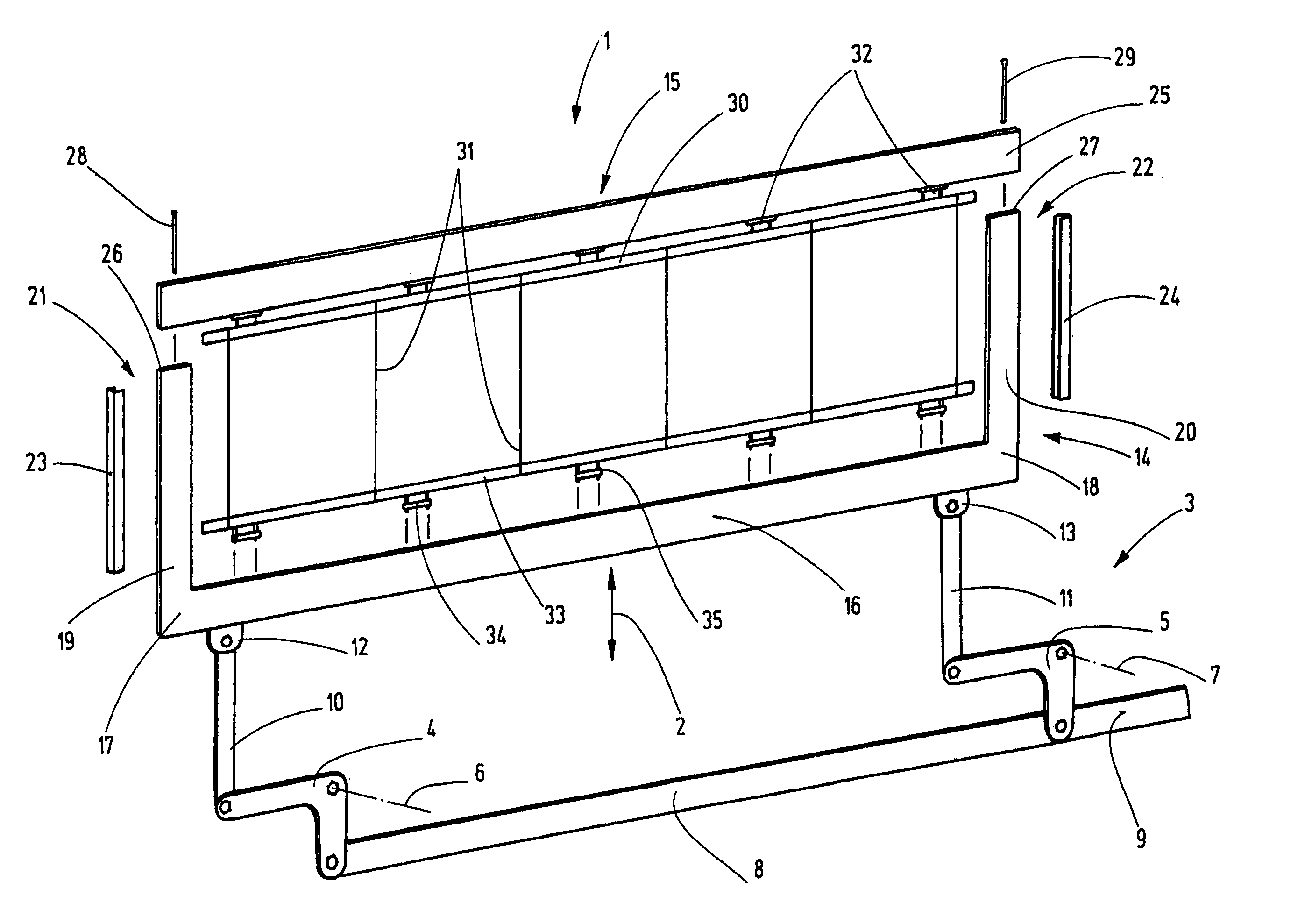
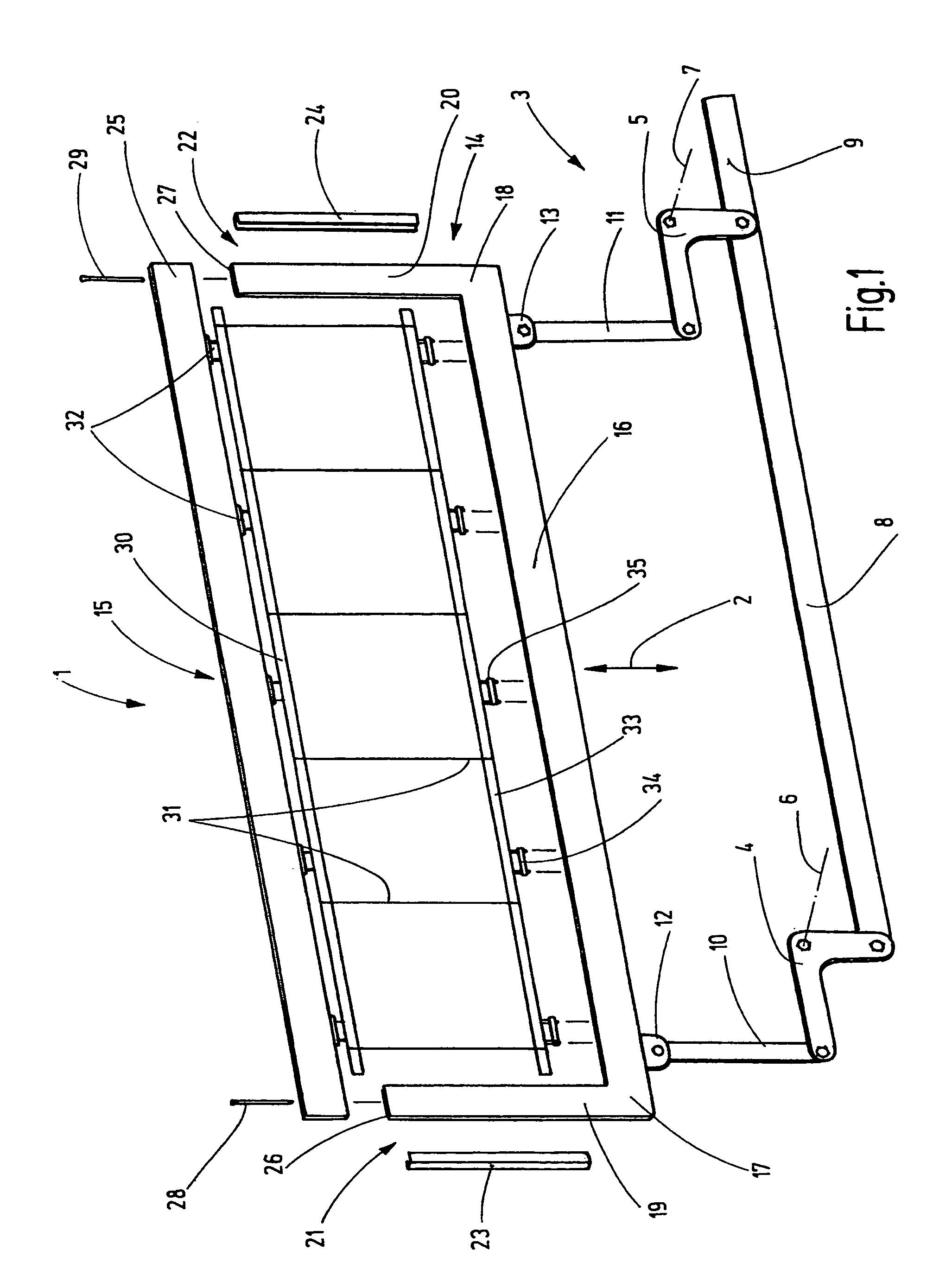
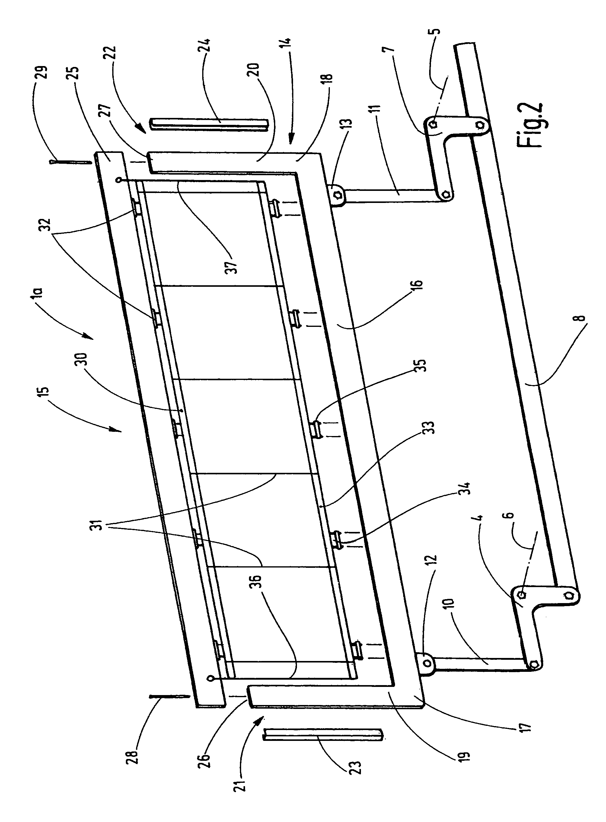
[0022]FIG. 1 shows a heald shaft 1 which is used for shed-forming in a weaving machine. To do so, the heald shaft 1 is driven to perform a vertical up-and-down movement as is symbolically indicated by an arrow 2 in FIG. 1. A drive device 3 is provided, said device imparting the heald shaft 1 with this motion. The drive device 3, for example, comprises a rod assembly that may include two or more rectangular levers 4, 5 that are supported so as to be pivotable about stationary rotational axes 6, 7. While the ends of these rectangular levers 4, 5—preferably facing downward when in use—can be connected to each other via a connecting rod 8 and to a shed-forming machine via a joint bar 9, the preferably approximately horizontally aligned arms of the rectangular levers 4, 5 are connected to the heald shaft 1 via joint bars 10, 11. The respective lower end of said joint bars is preferably connected to the rectangular levers 4, 5 in an articulating manner, and their upper end is connected to...


PUM


Abstract

The heald shaft (1) for weaving machines is divided into a machine-resident frame part (14) and a removable frame part (15). While the removable frame part (15) supports a heald mounting rail (30) that must be released from said frame part for a heald change, said removable frame part is associated with an additional heald mounting rail (33) that is releasably held on the lower shaft rod (16). The upper shaft rod (25), together with the two heald mounting rails (30, 33), forms a removable frame part (15). The lower shaft rod (16), together with the lateral supports (19, 20), forms a machine-resident frame part. Preferably, the lateral supports (19, 20) and the lower shaft rod (16) are rigidly connected to each other.

Description

CROSS REFERENCE TO RELATED APPLICATION[0001]This application claims the priority of European Patent Application No. 07 009 593.0, filed on May 14, 2007, the subject matter of which, in its entirety, is incorporated herein by reference.BACKGROUND OF THE INVENTION[0002]The invention relates to a heald (heddle) shaft for weaving machines.[0003]Weaving machines comprise heald shafts, said shafts bearing healds. The healds are disposed to guide warp threads and to form sheds. As a rule, the healds are accommodated on two spaced apart, parallel heald mounting rails, which, in turn are held on shaft rods. The shaft rods are part of a rectangular frame that is referred to as the heald shaft. In order to form sheds, said heald shaft is moved rapidly up and down. The shaft rods that are horizontally arranged during use support the individual heald mounting rails and, as a rule, their ends are connected via lateral supports. The lateral supports may be removed for the installation and deinstal...

Claims


Application Information

Patent Timeline
Patent Type & Authority Patents(United States)
IPC IPC(8): D03C9/00D03C9/06D03C13/00
CPCD03C9/0675
Inventor METTLER, FRANZ
Owner GROZ BECKERT KG
Why Eureka
Try Eureka