Apparatus for filling a sample volume defining device

a defining device and sample technology, applied in the field of apparatus for filling a sample volume defining device, can solve the problems of not filling cavities in a proper way, and achieve the effects of reducing cavity volume, facilitating predictability, and easy deformation permanen

Active Publication Date: 2006-10-12
BOULA MEDICAL AB
View PDF10 Cites 30 Cited by
  • Summary
  • Abstract
  • Description
  • Claims
  • Application Information

AI Technical Summary

Benefits of technology

[0028] Discussing next the scraping, the imaginary surface has been described above as an idealized surface entirely continuous with the reference surface. However, in practice any scraping device able to be kept in good contact with the reference surface must have a certain resilience, preferably the minimum resilience necessary for dynamic adaptation to the reference surface, which is preferably made of a harder material, without undue further deformation. Certainly the material in the scraping device should not be soft, in the sense that it easily deforms permanently. Suitable materials may include thermoplastics and preferably eleastomerics. The scraper resilience means that it will expand by deflection to a certain extent into the cavity volume, thereby creating an actual, or practical, opening surface for the cavity, generally so as to reduce the cavity volume somewhat. This may not be a problem as long as the reduction is predictable and foreseeable. In order to facilitate such predictability it may be of interest to minimize the volume deviation between the imaginary and practical surfaces.

Problems solved by technology

One problem when filling small cavities or voids or the like for obtaining the accurate and repeatable volume of a liquid sample, preferably a blood sample, is that the cavities are not filled in a proper way due to the formation of air bubbles in the cavities designed for the blood sample.
Another problem with known apparatus for testing of small volumes of a liquid sample / blood sample is to see when the apparatus is correctly filled.
Another problem is that the filling of known apparatus for testing of small volumes of a liquid sample / blood is dependent upon the direction of the apparatus when it is filled.

Method used


Image

  • Apparatus for filling a sample volume defining device
  • Apparatus for filling a sample volume defining device
  • Apparatus for filling a sample volume defining device

Examples


Embodiment Construction

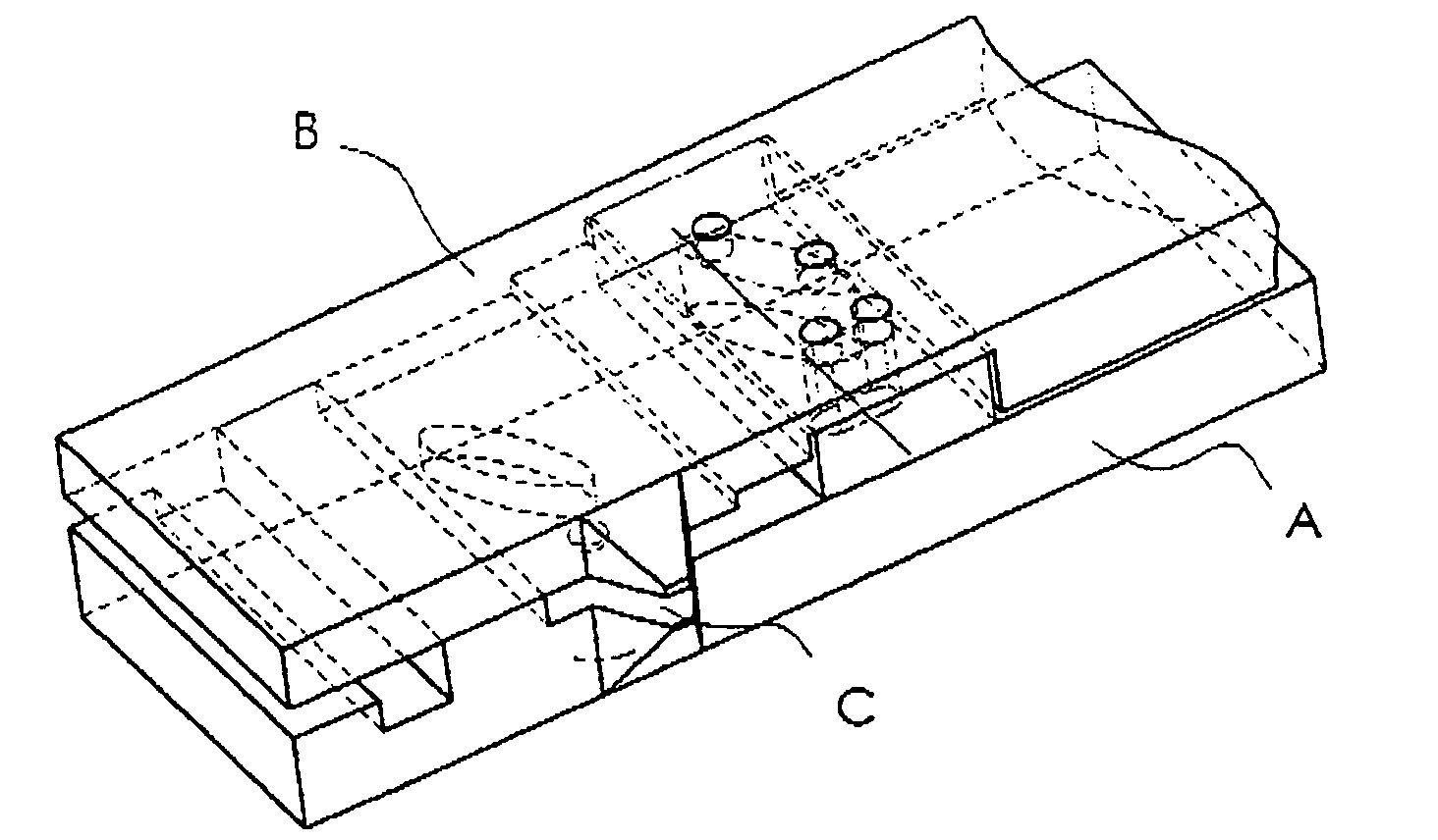
[0043] In FIG. 1 the apparatus according to a first embodiment comprises two bodies, i.e. a first body comprising a sledge A and a second body comprising a framework B, movable relatively to each other and in close contact. The apparatus forms a part of a disposable support (not shown), preferably in the form of a cassette, and the framework B is formed integrally with said support. The support comprises at least two chambers, one of which is filled with an accurately defined volume of diluent or lysing agent for dilution of a liquid sample, preferably a blood sample, and the other is used for achieving the dilution and mixing of the liquid sample.

[0044] The sledge A or the framework B or both are provided with suitable interengaging means (not shown) so that they can move relative to each other in close contact.

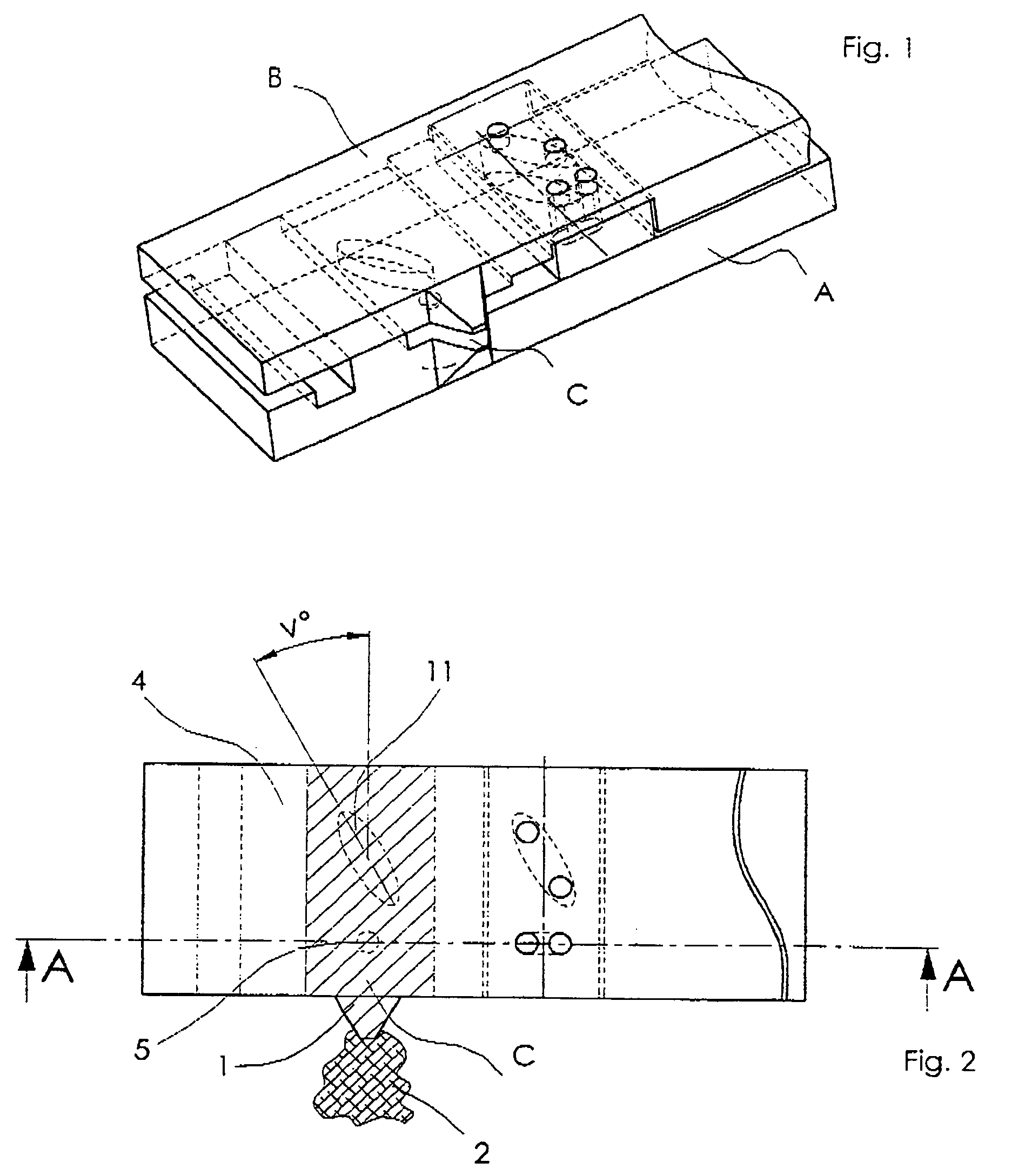
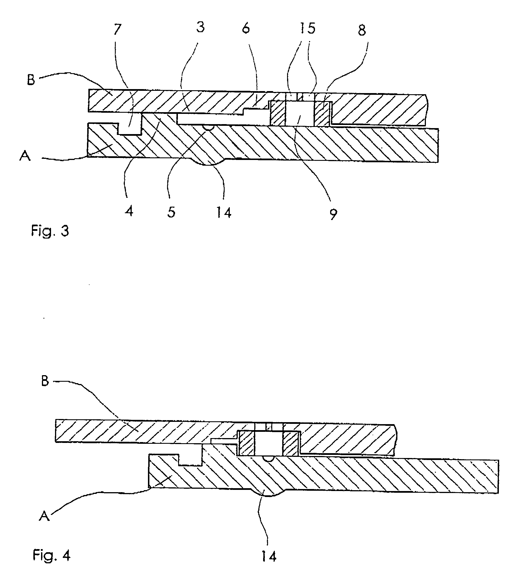
[0045] As can be seen from FIG. 3, between the sledge A and the framework B is a defined channel 3 arranged and provided with at least one inlet opening C for a liquid sam...


PUM


Abstract

An apparatus for filling a sample volume defining device for separating at least one small defined volume of a liquid sample from a relatively larger undefined volume of said sample, said device including a first body and a second body movable relative to each other, whereby said first body has at least one cavity in a surface thereof, said at least one cavity having said defined volume. One of said first or said second body has at least one inlet opening adapted to be placed in a drop of the liquid sample. A defined channel is provided between said first and second body, which channel has fluid connection with said at least one opening and at least beyond said at least one cavity whereby the dimensions of said channel being such that said channel and said at least one cavity is filled with said liquid sample.

Description

FIELD OF THE INVENTION [0001] The present invention relates an apparatus for filling a sample volume defining device, particularly a disposable sample volume defining device, for separating at least one small defined volume of a liquid sample from a relatively larger undefined volume of said sample, said device including a first body and a second body movable relative to each other, whereby said first body has at least one cavity in a surface thereof, said at least one cavity having said defined volume, and said second body includes a means slidable along said surface and over said at least one cavity upon relative movement of said bodies, whereby said defined volume is achieved in said at least one cavity. The liquid sample is a blood sample, for instance. BACKGROUND OF THE INVENTION [0002] In blood testing, it is of crucial importance to define an accurate volume of a blood sample, since such accurately defined volume is later on used for certain tests. The accurately defined volu...

Claims


Application Information

Patent Timeline
Patent Type & Authority Applications(United States)
IPC IPC(8): B01L3/00
CPCB01L3/502715Y10T436/2575B01L2200/027B01L2200/0605B01L2200/0684B01L2300/0654B01L2300/0825B01L2400/0406B01L2400/0475B01L2400/0478B01L2400/065B01L2400/0688G01N1/38Y10T436/25375B01L3/50273B01L3/00
Inventor BERNDTSSON, INGEMARNIKLASON, LENNART
Owner BOULA MEDICAL AB
Why Eureka
Try Eureka