Continuous fiber reinforced composite material additive manufacturing nozzle and printer

A reinforced composite material and continuous fiber technology, which is applied in the field of additive manufacturing, can solve the problems that the distance between the outlet of the inner head and the outlet of the outer head cannot be adjusted, the neutrality of the fiber composite material cannot be controlled, and the fiber filaments cannot be bonded together. Improvement of molding quality, easy cleaning of plugs, and reduction in quality

Active Publication Date: 2019-09-10
华明进
View PDF7 Cites 2 Cited by
  • Summary
  • Abstract
  • Description
  • Claims
  • Application Information

AI Technical Summary

Problems solved by technology

[0004] However, the current continuous fiber reinforced composite material additive manufacturing technology research is less, still in the research and development stage, there are many problems
For example, the resin cannot fully enter the interior of the fiber ribbon, and the fiber filaments cannot be bonded together by the resin, thus forming a cavity inside the printed workpiece, which seriously reduces the mechanical properties of the workpiece
In addition, the additive manufacturing of continuous fiber-reinforced composites is prone to clogging, resulting in the inability of fibers to come out or resin overflowing from the inside of the nozzle
[0005] The invention patent with the patent number 201611004458.X, a nozzle suitable for additive manufacturing of continuous fiber reinforced composite materials and the invention patent with the patent number 201611026706.0, a nozzle suitable for 3D printing of continuous fiber reinforced The nozzle is based on the additive manufacturing of continuous fiber reinforced composite materials, but the structure of the nozzle is more complicated, resulting in a larger size of the nozzle and a larger volume of the cavity containing the resin material. In addition, the distance between the outlet of the inner nozzle and the outlet of the outer nozzle cannot be adjusted. Controlling the Alignment of Fiber Composites

Method used


Image

  • Continuous fiber reinforced composite material additive manufacturing nozzle and printer
  • Continuous fiber reinforced composite material additive manufacturing nozzle and printer
  • Continuous fiber reinforced composite material additive manufacturing nozzle and printer

Examples


specific Embodiment approach 1

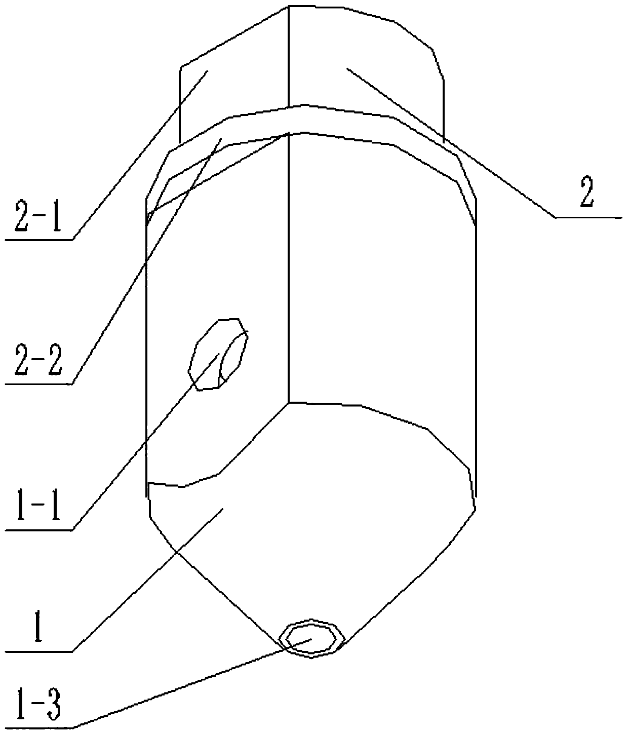
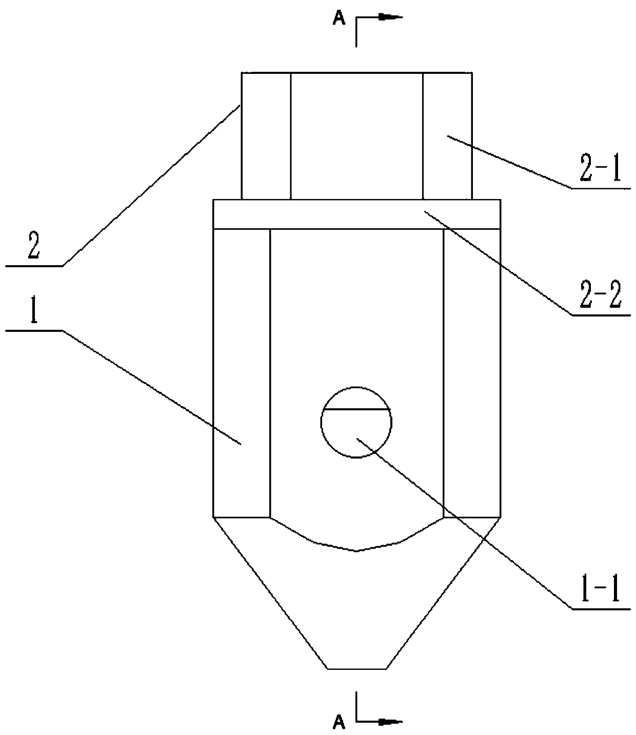
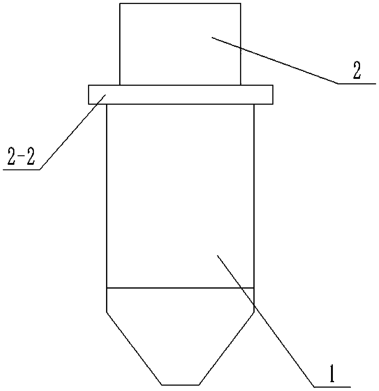
[0036] Combine below Figure 1-9 To explain this embodiment, the present invention belongs to the field of additive manufacturing. More specifically, it relates to a continuous fiber reinforced composite material additive manufacturing nozzle, which is composed of an outer nozzle 1 and an inner nozzle 2. The nozzle has a simple structure, a small size, and can be Improve the molding accuracy; in addition, the vertical distance between the outlet of the inner nozzle and the outlet of the outer nozzle is adjustable, which can control the centering of the fiber composite material and improve the molding quality.

[0037] The inner spray head 2 is threadedly connected to the inside of the outer spray head 1. The inner spray head 2 is provided with an inner cavity II2-3 for threading fibers, and the outer spray head 1 is provided with an inner cavity I1- containing resin material. 3. The inner cavity I1-3 is coaxial with the inner cavity II2-3, the outer nozzle 1 is also provided with...

specific Embodiment approach 2

[0039] Combine below Figure 1-9 To illustrate this embodiment, this embodiment will further explain the first embodiment. The upper end of the outer nozzle 1 is a cylinder, and the lower end is a cone. Two planes are symmetrically provided on the cylinder, and the connecting hole 1-1 Located on one of the planes, a positioning hole 1-2 is provided on the other plane, and the positioning hole 1-2 is a threaded blind hole. The two symmetrical planes facilitate the fixing of the outer nozzle 1 and the heat conducting block, and also facilitate the processing of the connecting hole 1-1 and the positioning hole 1-2. The connecting hole 1-1 is a through hole provided with an internal thread for connecting a throat pipe. The positioning holes 1-2 are used to match the holes on the heat-conducting block, so that the heat-conducting block and the positioning holes 1-2 are fixedly connected by screws, so that the outer nozzle 1 and the heat-conducting block are fixedly connected togeth...

specific Embodiment approach 3

[0041] Combine below Figure 1-9 This embodiment will be described. This embodiment will further explain the first embodiment. The inner nozzle 2 is a cylinder, the upper end of the inner nozzle 2 has a larger diameter than the lower end, and the upper end of the inner nozzle 2 is provided with a tightening head 2-1. The lower end of the head 2-1 is provided with a stopper 2-2, the inner cavity II2-3 penetrates the inner nozzle 2 and is coaxial with the inner nozzle 2, and the inner cavity II2-3 is composed of two cylindrical cavities. The diameter of the cylindrical cavity is larger than the diameter of the lower cylindrical cavity, and the junction of the two cylindrical cavities is an arc transition. Tightening the head 2-1 facilitates the rotation of the inner spray head 2 with tools such as a wrench, and can make the inner spray head 2 and the outer spray head 1 tightly connected, thereby preventing the resin from overflowing from the gap between the inner spray head 2 and...


PUM


Abstract

The invention belongs to the field of additive manufacturing, and particularly relates to a continuous fiber reinforced composite material additive manufacturing spray nozzle and a printing machine. The continuous fiber reinforced composite material additive manufacturing spray nozzle and the printing machine have the advantages that the continuous fiber reinforced composite material additive manufacturing spray nozzle comprises an outer spray nozzle and an inner spray nozzle, the spray nozzles are simple in structure and are small, and the forming precision can be improved; the vertical distance from an outlet of the inner spray nozzle to an outlet of the outer spray nozzle can be adjusted, accordingly, the centering properties of fiber composite materials can be controlled, and the forming quality can be improved; the inner spray nozzle is connected into the outer spray nozzle in a threaded manner, an inner cavity II is arranged inside the inner spray nozzle, fiber yarns can penetrate the inner cavity II, an inner cavity I for accommodating resin materials is arranged inside the outer spray nozzle and is coaxial with the inner cavity II, and a connecting hole which is communicated with the inner cavity I is further formed in the outer spray nozzle and is particularly formed in a side surface of the outer spray nozzle; continuous fiber reinforced composite material additive manufacturing can be implemented by the printing machine.

Description

Technical field [0001] The invention belongs to the field of additive manufacturing, and more specifically, relates to a continuous fiber reinforced composite material additive manufacturing nozzle and printer. Background technique [0002] Additive manufacturing technology is an emerging technology that is rapidly developing in the manufacturing sector. It is called "manufacturing technology with important symbolic significance of the third industrial revolution" and is listed as a key technology for strategic development by major developed countries. At present, additive manufacturing technology relies on cutting-edge technologies in multiple disciplines and has been applied in aerospace technology, automobile and home appliance manufacturing, biomedicine, food processing and other fields. Compared with traditional manufacturing technology, additive manufacturing three-dimensional rapid prototyping manufacturing technology omits the processing and manufacturing of product molds...

Claims


Application Information

Patent Timeline
Patent Type & Authority Patents(China)
IPC IPC(8): B29C64/209B29C64/336B29C64/118B33Y30/00B33Y40/00
Inventor 华明进
Owner 华明进
Why Eureka
Try Eureka