Upper garment

a technology for upper garments and garments, applied in the field of upper garments, can solve the problems of inability to provide comfortable wear feelings and high risk of upper garments losing their shape, and achieve the effect of less likely to lose its shape and comfortable wear feeling

a technology for upper garments and garments, applied in the field of upper garments, can solve the problems of inability to provide comfortable wear feelings and high risk of upper garments losing their shape, and achieve the effect of less likely to lose its shape and comfortable wear feeling

US20150164148A1Inactive Publication Date: 2015-06-18ASICS CORP

Image

  • Upper garment
  • Upper garment
  • Upper garment

Examples


Embodiment Construction

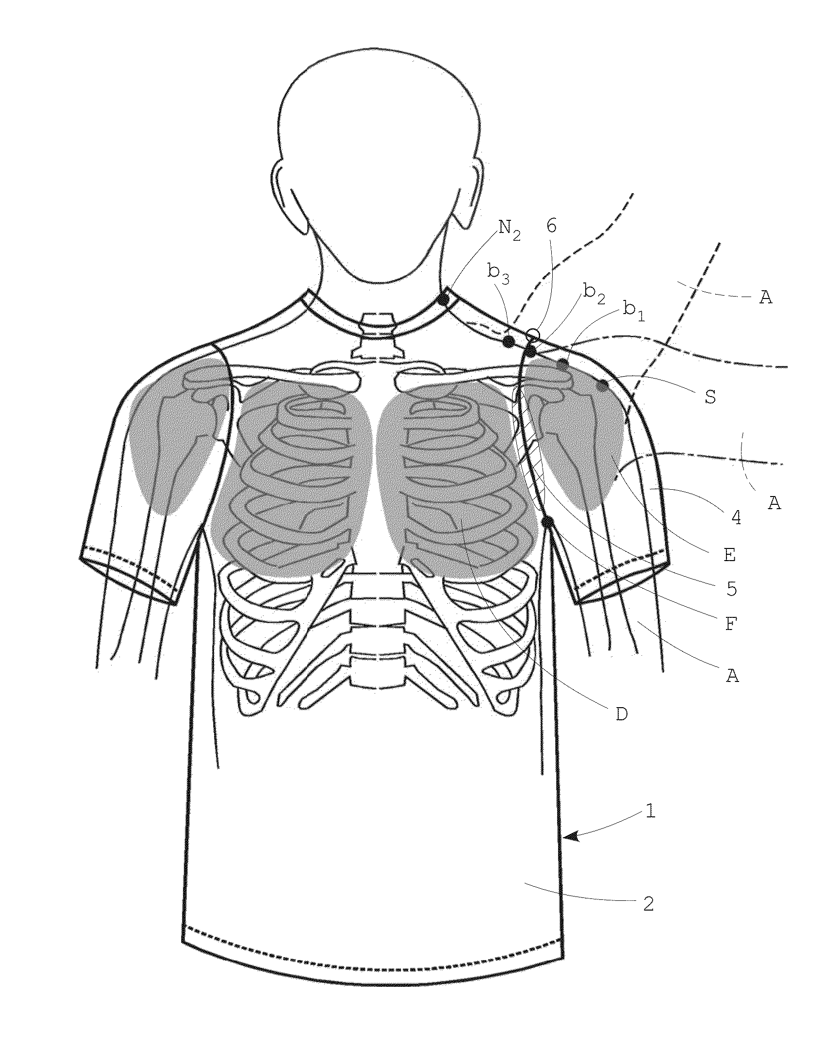
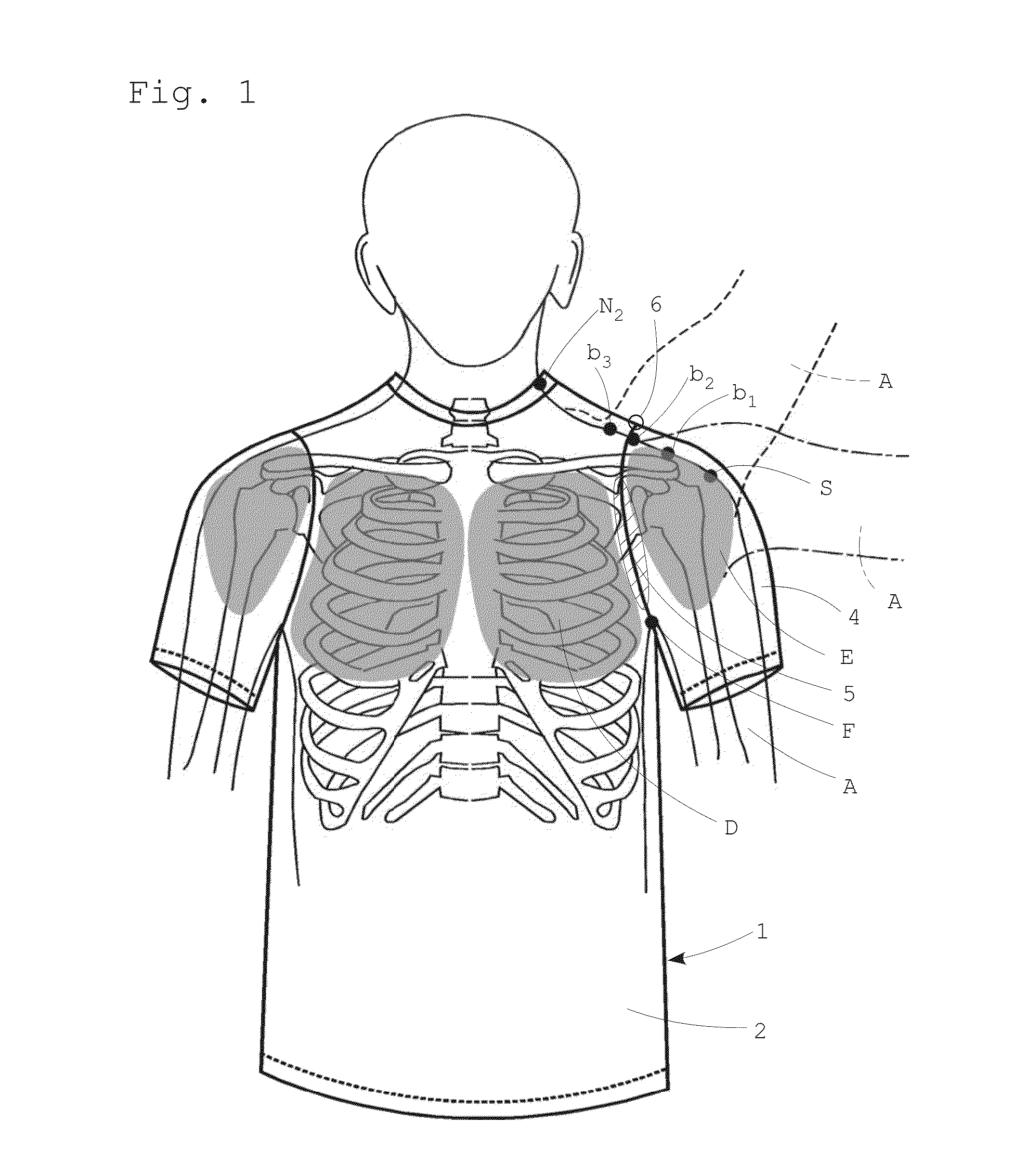
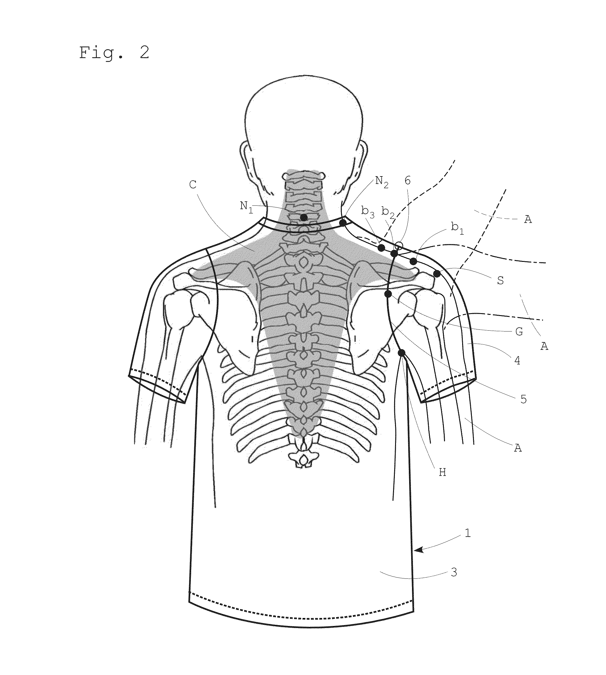
[0049]An upper garment 1 according to the present invention includes a front garment body 2, a back garment body 3, and sleeves 4. The sleeves 4 and the front garment body 2 are sewn to each other through armholes 5, and the sleeves 4 and the back garment body 3 are sewn to each other through the armholes 5.

[0050]A sleeve peak point 6 of each armhole 5 in the upper garment 1 according to the present invention is located between: a trapezius muscle stop point b1 on a shoulder ridge line L of a wearer in an arm A lowered state; and a trapezius muscle stop point b3 on the shoulder ridge line L of the wearer in an arm A raised state (indicated by a broken line in each of FIG. 1 and FIG. 2).

[0051]As the arm A is raised from its lowered state, as illustrated in FIG. 1 and FIG. 2, the position of the trapezius muscle stop point b1 on the shoulder ridge line L moves to b2 and then b3 toward a neck side point N2.

[0052]In FIG. 2, C denotes a trapezius muscle. Moreover, in FIG. 1, D denotes a ...


PUM


Abstract

The present invention has an object to provide an upper garment that prevents sleeves from dropping and a garment body from unnecessarily largely moving, is less likely to lose its shape, and can provide a comfortable wear feeling, even during strenuous exercise such as sports, particularly, when the arm is raised or rotated. A sleeve peak point 6 of an armhole 5 is located between: a trapezius muscle stop point b1 on a shoulder ridge line L of a wearer in an arm A lowered state; and a trapezius muscle stop point b3 on the shoulder ridge line L of the wearer in an arm A raised state, whereby an arm bending point during arm raising and the armhole 5 coincide with each other. Hence, when the arm A is raised or rotated, sleeves 4 are prevented from dropping, and a garment body is prevented from unnecessarily largely moving. Further, a portion of the armhole 5 on a front garment body 2 side is designed to pass through a deltopectoral groove between a deltoid muscle E and a pectoralis major muscle D of the wearer, whereby the upward retainability of the sleeves and the position stability of the garment body are further improved.

Description

TECHNICAL FIELD[0001]The present invention relates to an upper garment that is less likely to lose its shape and can provide a comfortable wear feeling even during strenuous exercise such as sports, because armhole shapes of sleeves of the upper garment are devised.BACKGROUND ART[0002]Up to now, upper garments that are expected to provide wear feelings improved by devising sleeve shapes are disclosed in Patent Literature 1 and Patent Literature 2.[0003]Unfortunately, these upper garments are likely to lose their shapes and cannot provide comfortable wear feelings during strenuous exercise such as sports.[0004]A conventional upper garment 11 used for sports shirts and the like includes a front garment body 12, a back garment body 13, and sleeves 14. The sleeves 14 and the front garment body 12 are sewn to each other through armholes 15, and the sleeves 14 and the back garment body 13 are sewn to each other through the armholes 15.[0005]Examples of the sleeves 14 having shapes standar...

Claims


Application Information

Patent Timeline
18 Jun 2015
Publication
US20150164148A1
IPC
A41B1/08
CPC
A41B1/08; A41D27/10; A41D2400/38
Inventors
TAKAMOTO, YOSHIKUNI; KOGA, YUTAKA