Tuned liquid damper of a wind turbine

a wind turbine and liquid damper technology, which is applied in the direction of mechanical equipment, machines/engines, electric generator control, etc., can solve the problems of reducing the lifetime of the components affecting the operation of the wind turbine, so as to save the weight of the components, facilitate the arrangement, and eliminate the effect of wind turbine vibrations

Active Publication Date: 2015-06-18
SIEMENS GAMESA RENEWABLE ENERGY AS
View PDF26 Cites 1 Cited by
  • Summary
  • Abstract
  • Description
  • Claims
  • Application Information

AI Technical Summary

Benefits of technology

[0008]The wind turbine may comprise a damper system to at least partially eliminate an unwanted movement of the wind turbine resulting from wind loads, whereby the damper system comprises a liquid damper. The damper system can be arranged at a non-rotating part of the electric generator.
[0028]In addition, an aisle can be kept free within the generator. Thus, service personnel can pass through the generator and can easily reach the rack and the damper system while passing through the generator along the aisle.

Problems solved by technology

Vibrations reduce the lifetime of the components of the wind turbine and are therefore unwanted in the wind turbine.
This shows the disadvantage that the tanks of the tuned liquid dampers take up space in the tower of the nacelle of the wind turbine.
This shows the disadvantage that the load transferring structure is weakened by the holes, thus the load transferring structure needs to be built with more material to provide the same strength as without bolt holes.
This increases the weight of the wind turbine and thus the costs spent on the material and transportation of the wind turbine.
In addition, these details increase the complexity of the casted structure and thus the overall costs of the wind turbine.
While the wind interacts with the wind turbine, loads and vibrations are induced into the wind turbine.
These loads and vibrations induced into the wind turbine lead to a vibration of the wind turbine.
A vibration reduces the lifetime of the wind turbine especially when the eigenfrequency is reached.
A hole in the non-rotating part of the generator may weaken the structure of the non-rotating part.

Method used


Image

  • Tuned liquid damper of a wind turbine
  • Tuned liquid damper of a wind turbine
  • Tuned liquid damper of a wind turbine

Examples


Embodiment Construction

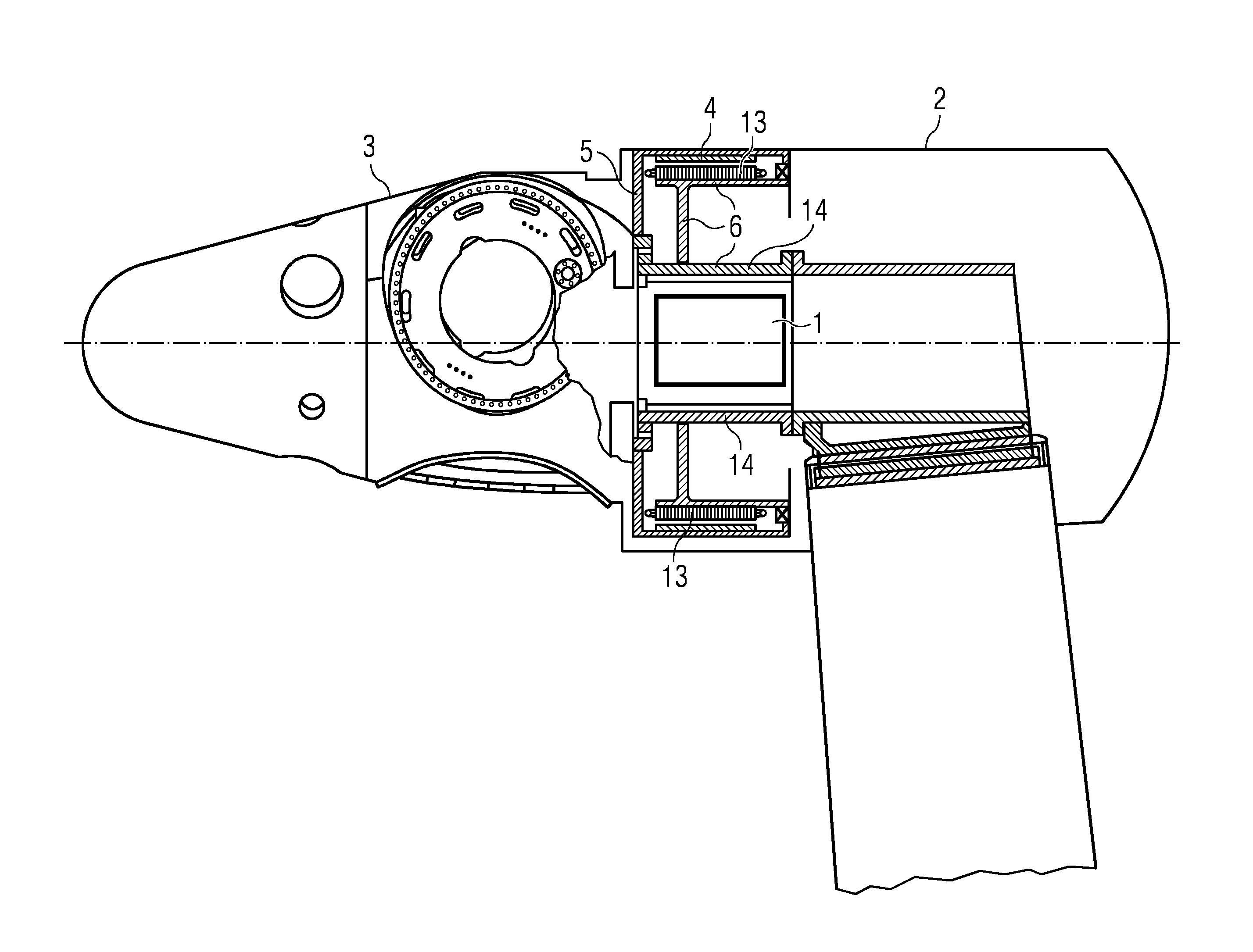
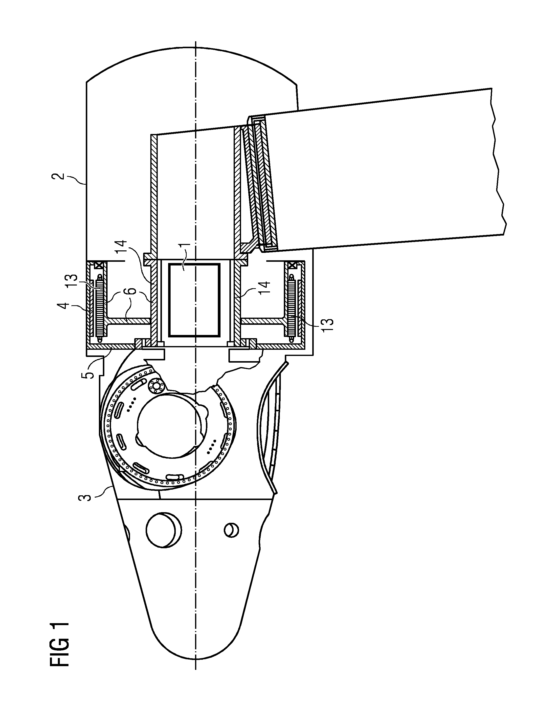
[0032]FIG. 1 shows an embodiment of a wind turbine with a damper system 1. The wind turbine comprises a nacelle 2 and a rotor hub 3. The rotor hub 3 is connected to the rotor 5 of the electrical generator 4. The rotor hub 3 is prepared to be equipped with rotor blades.

[0033]The electrical generator 4 comprises a rotor 5 and a stator 13. The stator 13 is supported by the support structure 6 that is connected to a shaft 14. The stator 13 the support structure 6 and a shaft 14 form the non-rotating part of the generator. The shaft 14 of the electrical generator 4 is connected to a support structure within the nacelle 2 of the wind turbine.

[0034]When the wind turbine is in operation, the wind interacts with the rotor blades and the rotor hub 3 rotates together with the rotor 5 of the electrical generator 4. The rotor 5 of the electrical generator rotates in respect to the stator 13 of the electrical generator 4.

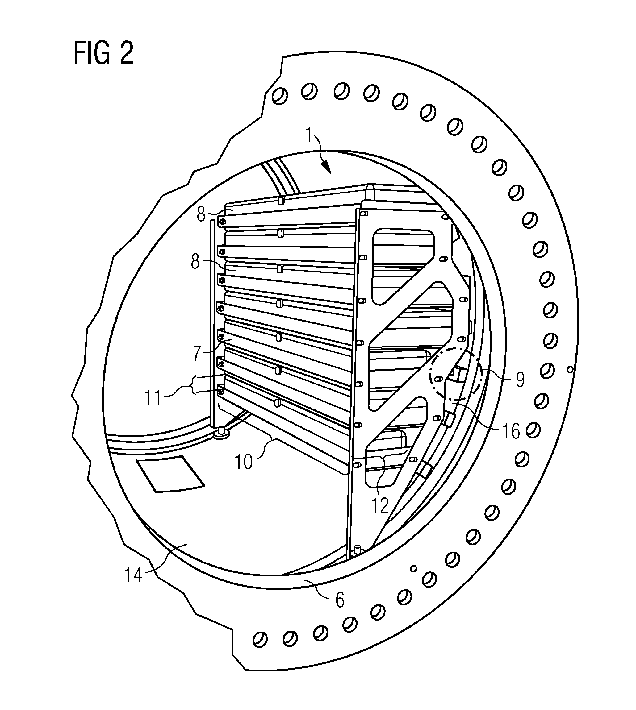
[0035]A cavity is formed within the non-rotating part 6 of the generator 4. ...


PUM


Abstract

A liquid damper in a wind turbine is provided. A damper system of a direct driven wind turbine is disclosed, whereby the wind turbine comprises a nacelle, a rotor hub and an electric generator. The electric generator comprises a rotor and a non-rotating part. The rotor hub is connected to the rotor of the electric generator. The non-rotating part of the generator is connected to the nacelle. The wind turbine comprises a damper system to at least partially eliminate an unwanted movement of the wind turbine resulting from wind loads, whereby the damper system comprises a liquid damper. The damper system is arranged at a non-rotating part of the electric generator.

Description

CROSS REFERENCE TO RELATED APPLICATIONS[0001]This application claims priority to EP Application No. EP 13196821.6 having a filing date of Dec. 12, 2013, the entire contents of which are hereby incorporated by reference.FIELD OF TECHNOLOGY[0002]The following relates to a liquid damper in a wind turbine.BACKGROUND[0003]A wind turbine comprises a tower, a nacelle, and a rotor. The rotor is rotatable connected to the nacelle of the wind turbine and the nacelle is rotatable connected to the tower. The rotor comprises rotor blades and a rotor hub. The wind interacts with the rotor blades. This interaction leads to a rotation of the rotor hub. The rotational energy is transmitted to an electric generator and is there transferred into electrical energy. The wind induces vibrations in the wind turbine. Vibrations reduce the lifetime of the components of the wind turbine and are therefore unwanted in the wind turbine.[0004]The wind turbine comprises a passive damper system to reduce or elimin...

Claims


Application Information

Patent Timeline
Patent Type & Authority Applications(United States)
IPC IPC(8): F03D11/00F03D7/02F03D9/00
CPCF03D11/0075F03D7/0296F03D9/002F03D1/00F05B2240/14F05B2260/302F05B2260/964F03D9/25F03D15/00F03D15/20F03D80/00F03D80/88Y02E10/72
Inventor JENSEN, DANIEL KAI
Owner SIEMENS GAMESA RENEWABLE ENERGY AS
Why Eureka
Try Eureka